Manufacturing is changing. Manufacturers are seeing greater pressures from the consumer for improved product quality and faster time to market. This pressure is felt across the entire product development cycle from design and engineering to tooling and production. And, each step of the process has its own challenges.
As the pressure for improved product performance rises, mold builders are experiencing increases in part complexity that require more complex tooling, new material and molding technologies, “first-time-right” requirements and competitive pressures from other mold shops. All of this means a shop must adapt or be left behind.
Simply buckling down and working harder has been the common approach to address these increased demands. Mold builders have invested in bigger, faster and more high-tech machinery to meet the new production needs, which has required a large investment. This, in turn, has limited growth in other areas of the business that could support innovation and further business growth.
Today, a shift is taking place in the approach to work: working smarter rather than harder to meet the increased demand. Mold builders are now searching for ways to increase the use of existing in-house tools while improving the quality of the final product.
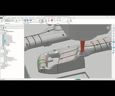
A popular working-smarter approach is using software to aid the programming of machinery and to gain tooling design insights. CAM and CAE software play a key role in these efforts, as they both help to increase the availability of information earlier in the manufacturing process before cutting any steel. More data means mold builders can make better decisions, which gives them the ability to provide a better product to their customers and increase quoting accuracy.
Today, mold builders can adjust part geometry on the fly with geometry optimization tools that help them explore different configurations for improved moldability without multiple iterations with the designer.
CAM and CAE Advances
CAM and CAE work together to improve the mold manufacturing process. Mold builders can use CAM to program planned tool paths, to decrease tool collision and to identify effective paths to use machine time optimally. Mold builders can use injection molding CAE simulation to assess mold design options and their impact on the final plastic product before programming tool paths to ensure that the machine cuts the right shape.
Overall, the value of simulation is rooted in the ability to make a better decision sooner. Simulation enables the mold builder to explore different tooling configurations, including gate locations and runner sizes, to measure the impact on the quality of the plastic product and the speed of production. Mold builders can also use this information to justify investment in new technologies or different design approaches, which could change the way machines cut steel, making a part easier to manufacture.
Traditionally, mold builders or molders apply injection molding simulation to a project using a trial and error approach when they discover a problem. The molder sets up a configuration, runs the analysis, evaluates the results by comparing them to a specification and then repeats the process until he or she produces a satisfactory result that meets the required guidelines.
Although this approach provides the molder with a result that meets specification and solves the issue, the molder never really knows if the results are optimal. A trial-and-error approach limits a user’s configuration, iteration, and variation options, as the end user will only be able to try a few different approaches based on his or her experience with what the best options are in a set amount of time. The user can determine a better configuration within this time frame, but he or she may not discover the best configuration.
Mold builders also use injection molding simulation early in the design phase to gain advanced insights, such as proper gating placement, cooling line placement, cooling complexity (conformal cooling versus drill and plug), material shrinkage and so on. They employ simulation in the cloud to expand the number of scenarios for parallel analysis rather than serial analysis. The cloud also provides on-demand resources at the click of a button without the need for local infrastructure support or local hardware investment that may sit idle most of the time.
Here is how it works: The end customer supplies a mold builder with a part model for a mold build. If the mold builder requires additional designs options or a reduction in wall thicknesses, he or she must work with the part designer to incorporate the changes. At best, this approach yields an updated model to review. In some cases, an updated design is not possible because of a tight specification. In other cases, design variations are possible, but the wait time for an updated part model cuts into overall mold design and build time, which leaves less room to address any issues that arise during the build process.
Adding Optimized Geometry to Simulation
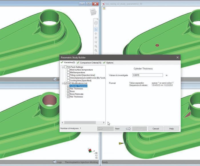
Today, mold builders can adjust part geometry on the fly (for example, remove ribs and bosses or adjust wall thickness) with geometry optimization tools that help them explore different configurations for improved moldability without multiple iterations with the designer. These design updates can also reduce extra features, such as slides and undercuts, reducing tool complexity. Combining geometry optimization with injection molding simulation goes one step further and illustrates the positive impact of the design change on the final part, which provides justification for the changes and increases the mold builder’s credibility with the customer.
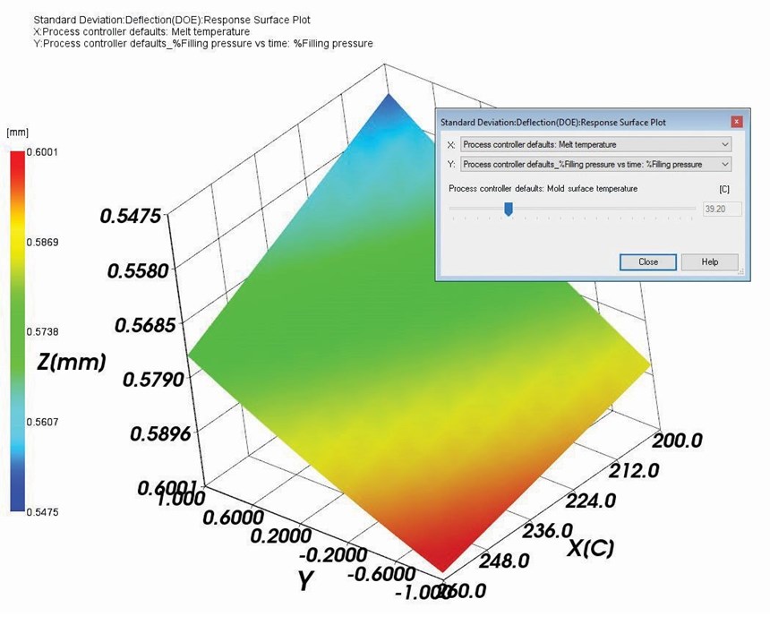
Injection molding simulation analysis, such as Design of Experiments (DOE), enables a mold builder to explore all molding process conditions automatically by specifying a processing window for a given design (high- and low-end melt temperature, filling time and so on). The analysis will then determine and analyze all possible combinations and identify the optimal quality based on the end user’s design criteria. With geometry optimization, the mold builder can go one step further and analyze the impact of wall thickness and processing conditions simultaneously where the mold builder specifies the part areas requiring adjustment. The analysis will then determine and analyze all possible processing combinations along with wall thicknesses to identify the optimal combination based on the end user’s criteria. This design approach greatly reduces all manual, individual analysis set up.
Once the analysis is complete, the mold builder uses investigation tools to examine every scenario simultaneously rather than one at a time. For example, to determine the weld line location, a DOE analysis will produce 20 different scenarios to evaluate the impact of wall thickness in a specific area. Reviewing 20 combinations one at a time through a side by side comparison is a challenge. However, DOE investigation tools use a slider bar to vary the wall thickness of the model as it moves. This shows the movement of the weld line location as the wall thickness changes. Reviewing this impact in a single view cuts the time it takes to interpret the results in half.
Mold builders who take advantage of the added insights from flow simulation, geometry optimization and investigation tools will reduce mold rework, increase shop throughput and deliver better, higher quality tools to their customers with confidence that the final product will be right from the first shot.
About the Contributor
Mark Hennebicque is a business line manager at Autodesk Inc.
Related Content
Three Good Reasons to Switch from Three- to Five-Axis Machining in Moldmaking
Five-axis machining technology is a great tool in the moldmaker toolbox.
Read MoreHow to Improve Your Current Efficiency Rate
An alternative approach to taking on more EDM-intensive work when technology and personnel investment is not an option.
Read MoreFour Micro Tooling Considerations
Issues involving gating, ejection, mold splits and direction of pull are of special concern when it comes to micro tooling.
Read MoreTips for Tackling Mold Design, Machining, Cutting Tool and Wear Challenges
Tips for tasks ranging from reducing risk in part design and taking advantage of five-axis machining to refining cutting tool performance and reducing wear with guiding and centering systems.
Read MoreRead Next
Software Technology Is More Versatile, Efficient and Simplified
Software suppliers are working diligently to provide moldmakers with relevant but easy-to-use solutions that speed processes and lower costs.
Read MoreHow to Use Strategic Planning Tools, Data to Manage the Human Side of Business
Q&A with Marion Wells, MMT EAB member and founder of Human Asset Management.
Read MoreHow to Use Continuing Education to Remain Competitive in Moldmaking
Continued training helps moldmakers make tooling decisions and properly use the latest cutting tool to efficiently machine high-quality molds.
Read More

