Digital Manufacturing Insights
When it comes to digital manufacturing, International Mold Corp. uses scanning, reverse engineering, and inspection, but has not ventured into 3D printing. A team attended an integrated digital manufacturing conference to learn more. Here is what they discovered.
When it comes to digital manufacturing, International Mold Corp. (IMC) (Clinton Township, Michigan) uses scanning, reverse engineering, and inspection (a Faro Edge Scan Arm with Polyworks software and Polyworks Inspection), but has not ventured into 3D printing. So, a team from IMC attended an integrated digital manufacturing conference presented by CATI (Computer Aided Technology) that covered scanning, reverse engineering, inspection, and 3D printing technologies.
Engineers demonstrated scanning and reverse engineering using Creaform Handyscan and Creaform software. Although the technology is different from that of IMC, the principles are the same: scan to a point cloud, convert points to a .stl file and then reverse engineer the object.
For inspection, the CATI team used scans and probes and then compared results to the master data applying standard GD&T principles. This technology is impressive, as it seems almost to replace traditional CMM. Although CMM seems is automated, the scanning technology is portable.
Now by using laser scanning and reverse engineering shops can recreate anything into a digital world, for example, nonexistent or lost mold and tool designs, one-of-a-kind art projects or obsolete car parts. The possibilities are endless.
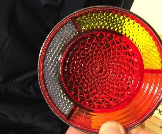
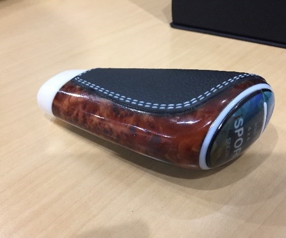
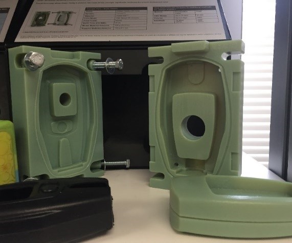
I want to tell you that this was the most impressive technology I saw that day, but it wasn’t. The 3D printing potential I witnessed blew my mind. I am familiar with 3D printing, but I was not prepared for the art of photorealism 3D printers are applying to 3D-printed prototype parts today (see photos).
I hope this enlightened fellow mold and toolmakers as to some of the current digital manufacturing technologies on the market today. Good luck out there, it is truly a digital world!
Related Content
-
How to Eliminate Chatter
Here are techniques commonly used to combat chatter and guidelines to establish a foundation for optimizing the moldmaking process.
-
It Starts With the Part: A Plastic Part Checklist Ensures Good Mold Design
All successful mold build projects start with examining the part to be molded to ensure it is moldable and will meet the customers' production objectives.
-
Laser Welding Versus Micro Welding
The latest battle in finely detailed restoration/repair of mold materials.


