Detecting Water Flow Restrictions
A look at how taking the time and data to analyze a mold problem will help you repair it right—and permanently—the first time.
The 32-cavity mold landed on our bench and looked like any other mold than had been run hard and put away wet. It was covered in grime and resin dust and after a 90-mile truck ride, was still dripping water out of every fitting. The only information we had was a verbal comment that “It ran OK”. It was our challenge now to get the mold cleaned up, checked out and back to the molder as quickly as possible. Looked simple enough—from the outside.
Since the tool came with zero documentation, we had little to go on that would help us create an accurate maintenance plan. The upside was since it was the first time our shop had ever seen or worked on the mold, it would now benefit from a fresh set of eyes and methods of cleaning and repair. Many times, when a mold is run and problems develop, the corrective action plan is focused on doing whatever is necessary to get a mold producing parts again, which usually translates into shims and process tweaks over several production runs. There just doesn’t seem to be enough time or data to analyze a problem—and repair it right, and permanently—the first time.
Types of Obstructions
Usually overlooked until a problem arises, water lines and bubblers can become caked with calcium and rust. Other restrictions—such as small pieces of plastic, rubber, nylon tape (from pipe fittings) and broken off chunks of brass, steel and even thread seal paste—can accumulate in areas hard to see. Sometimes these type of clogs are either caught in filters or are easily seen after the mold is disassembled as they damn up around o-rings or any reduction of diameter like water fountains/bubblers or baffles. Other times, the restriction is inside a plate or cavity block making identification and removal even more difficult.
Production techniques to remove these obstructions are limited to reversing the direction of water or air, hoping to dislodge it—but seldom work—or they land somewhere else in the mold.
On the bench, molds are disassembled to individually check each component, such as a bubbler, to locate the restriction, then blow it out or remove it with an appropriately sized piano wire or pick. A popular bench test involves blowing air through lines by hand with a nozzle while listening to the sound and feeling the amount of air coming out of the outlet line or fountain with the other hand. This subjective method then verifies that everything “feels OK” from line to line. Gauging the amount of air blowing through a water circuit is difficult and can vary from repair tech to repair tech depending upon technique and tools used. A small thing like using an air nozzle with a rubber tip that seals tight against whatever you are blowing through can make a huge difference in the feel and sound of the air coming out of fountains or the outboard fitting. As in most things in mold maintenance—technique is everything.
Cooling Is Critical, Ya Think?
During a production run, the cooling time in the mold often gets extended as a corrective action for product-related issues such as flash, burns, parts sticking, long gates or dimensional defects. Other defects and mold problems can be caused—or aggravated—by incorrect cooling through plating of the waterline from calcium/rust build-ups or reduced GPMs through restricted water lines. Obviously this is not a new revelation—but cooling channels that digress slowly are many times the last thing to check when the effects are finally realized in the part. When they are, process changes are implemented to override the effects of the reduced cooling. If one of these process tweaks works, the toolroom may not be alerted that the mold ever had a problem, so the issue does not get resolved when the mold gets pulled for PM because process was able to work around it.
Two Types of Flow Measurement
There are two types of water circuit checks. The first is a comparative analysis, where the water flow (GPM) of one circuit is compared to a like circuit of the same ID and configuration.
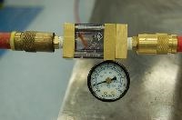
For instance, say you wanted to check the water circuits of a 16-cavity mold and the pattern was 4 x 4 or four rows of four cavities. You would then check each of the four rows, one at a time to determine if there was a restriction somewhere in the row of four cavities, demonstrated by a reduced GPM readout in one of the lines. On our bench manifolds, we installed a shut-off valve to reduce the inlet line pressure to 10 psi, which puts the GPMs in the center of the flow meter gauge (1.5 GPMs). This now becomes our test setting for the rest of the water lines. This will allow an internal restriction to be easily recognized by an increase in inlet pressure in combination with a reduction of GPMs
(see Photo).
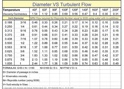
The second check involves the calculation of a Reynolds number to determine if the circuit has turbulent or laminar flow. To find out if a water line or circuit has turbulent flow capability, the best method is to install a flow meter (set up with quick disconnects) on a mold water line (checking only one line at a time) while in production at the press, so water temps and additives can be factored in. Water temperature, additives ratio, viscosity, pressure and waterline size all affect GPM—thus turbulent flow. A common rule of thumb without all the calculations is anything over 2.0 GPMs usually results in turbulent flow—but see Chart 1 for a better breakdown and remember that a favorable comparative flow rate does not verify turbulent flow within a circuit.
What Did It All Mean?
Uneven plate cooling or hotspots from minor reductions of GPMs can have major consequences on the part and cycle time. For instance, our mold had a GPM reading of 1.5 GPMs with 11 PSI of water pressure through a ¼ line and the circuit above it had .5 GPMs and the pressure spiked to 16 PSI—meaning cooling efficiency of this line had a restriction that reduced the GPM 30 percent, which could develop into issues with this product in the future. When we relayed this information to the molder, his process tech said he thought the mold might have had gate issues in that row, but wasn’t sure. Anyway, they needed it back quickly so we simply documented our findings for future reference because one of these days …
Related Content
How to Use Scientific Maintenance for More Accurate Mold and Part Troubleshooting
Discover how adopting scientific maintenance approaches helps improve mold lifespan, minimize failures, and optimize production outcomes.
Read MoreHow to Automate Process and Design
Moldmakers can improve their operations and stop wasting time by taking these six steps for process and design automation.
Read MoreWhat Is Scientific Maintenance? Part 1
Part one of this three-part series explains how to create a scientific maintenance plan based on a toolroom’s current data collection and usage.
Read MoreIndiana Mold Builder Decatur Mold Offers a History of Grit and a Future of Innovation
Decatur Mold Tool and Engineering Inc. serves as a tooling tour guide, helping busy tooling managers reduce uncertainty, lighten workload.
Read MoreRead Next
Are You a Moldmaker Considering 3D Printing? Consider the 3D Printing Workshop at NPE2024
Presentations will cover 3D printing for mold tooling, material innovation, product development, bridge production and full-scale, high-volume additive manufacturing.
Read MoreReasons to Use Fiber Lasers for Mold Cleaning
Fiber lasers offer a simplicity, speed, control and portability, minimizing mold cleaning risks.
Read More


