Design Right the First Time
Simulation of both the induction heating and injection molding processes optimizes cycle time and final part results.
The benefits of rapid heating and cooling within injection molding are well-understood. For example, increasing the temperature of the tool to a polymer’s glass-transition temperature or higher can help achieve a high-gloss, high-quality surface finish on the part along with stronger weld lines, elimination of aesthetic surface defects and lower injection pressures. In fiber-filled parts, surface quality is improved significantly due to the formation of a resin-rich surface layer. However, these benefits can be diminished by the long cycle times necessary for the mold to heat up prior to injection and to cool post-filling.
Rapid heating and cooling technologies that are widely used today, such as pressurized water, steam or electrical cartridges, have limited means to control exactly where the mold is heated. Heat is dispersed throughout the entire mold, so it takes a long time for the entire mold to reach the desired temperature, and since the cooling system subsequently needs to draw a large volume of heat away from the tool, cooling time is increased as well.
Inefficiency is not the only drawback of these types of heating and cooling technologies. To reduce warpage, it is sometimes desirable to maintain different temperatures at different parts of the mold. Separate core and cavity temperatures can be achieved using typical heating and cooling methods, but it is not easy to create controlled temperature variations across each individual mold surface, which is ideal for parts that require areas of both high and low gloss on the same surface. Steam and water heating also have an upper temperature limit that can be reached economically, which prevents their application to high-temperature polymers such as polycarbonate or polyamide 6 (nylon).
Induction Heating
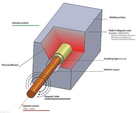
Induction heating is a good alternative to these traditional heating and cooling approaches. The fundamental concept behind induction heating is to heat only the surface of the mold, which leaves the bulk of the tool cold and resolves many of the aforementioned challenges. Heating is achieved by applying a high-frequency alternating current (typically 10 to 100 kHz) through an induction coil. This, in turn, generates a magnetic field that induces eddy currents on surrounding metal objects (see Figure 1). These electrical currents flow in a circular path and generate Joule heating, which is the generation of heat from a current flowing through a conductor (similar to the element of a lightbulb). The conductor is a very thin layer (often less than 1 mm) of metal, such as the magnetic tool steels that are used as inserts.
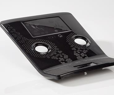
Induction heating provides more flexibility for controlling which areas of the mold are heated and what temperature each of those areas reaches. Specific spots on the mold surface can be targeted for heating by using highly magnetic inserts in those areas to focus the electromagnetic effects. For parts with varying surface textures, applying these inserts in locations where high gloss is required can result in significantly improved surface quality (see Figure 2).
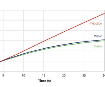
With induction heating, the temperature that a particular area of the mold reaches is directly proportional to the amount of time the current is applied. While the rate of heating decreases over time with water and steam heating methods, there is no practical upper limit to how hot the mold can get with induction heating (see Figure 3). This means the mold can be heated appropriately for high- and low-temperature polymers with the added benefit of shorter cycle times and lower energy consumption.
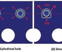
The induction heating process can be made more efficient by machining grooves into the channels where the induction coils will rest (see Figure 4). This will focus nearly all of the heating power on the molding zone, nearly doubling efficiency. More heat is generated with less power in the area where it is desired, while the bulk of the mold is heated very little. This results in reduced cooling time and reduced overall mold cycle times.
Designing an induction heating system comes with its own set of challenges, however. The layout of the coil needs to accurately follow the curvature of the part, and it is often designed in the core around other mold components (for example, hot runners, nozzles, lifters, sliders and cooling channels). In addition to the shape and placement of the induction coil, other variables also need to be optimized to ensure that the induction heating system performs as desired. These variables include mold materials, frequency, current and cooling system design.
Process Insight
Simulation provides a relatively low-cost option for experimenting with technologies such as induction heating, enabling molders to evaluate the potential benefits for individual applications early in the process. It also can ensure that a system is designed correctly and will perform as desired.
Simulation of the induction heating process, combined with injection molding simulation, shows not only the effect of coil placement and process settings on the mold temperatures, but their effect on the final plastic product as well. Insight gathered from these analyses can help users make informed decisions about the placement and design of induction coils, cooling channels and other mold components to optimize the final product and cycle times.
The two most important things to review when evaluating an induction heating system are 1) that heating is occurring in the proper locations on the mold and 2) that the surface is being heated to the desired temperature.
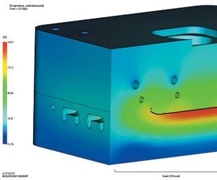
Temperature plots show the temperature over the entire thickness of the mold at any time in the molding process (see Figure 5). Critical points on the mold surface must remain above the glass-transition temperature as the melt front passes in order to ensure a high-quality surface finish on the part. Temperature plots also can help molders evaluate final part warpage, the time required to heat the mold surface and the cooling time required to reach a safe ejection temperature.
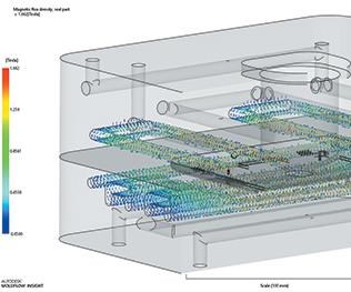
Potential drawbacks of heating induced through magnetic fields that are generated by alternating current are not self-evident. Additional evaluation tools are available that specifically isolate and identify any issues that may occur with the electromagnetic heating process itself. Magnetic field plots identify the strength of the heating effect throughout the mold to ensure it is concentrated on the mold surfaces that are actually forming the part (see Figure 6). Joule heating studies can identify which areas of the mold are heated and ensure there is a uniform distribution of the heat in targeted areas. Together, these tools can help design and position the coil properly and apply appropriate settings to achieve the best results with induction heating.
Induction heating provides an efficient alternative to the typical approaches to rapid heating and cooling of injection molds. While it comes with its own set of design challenges, simulation software can help ensure the system is designed properly and will perform optimally.
Related Content
How to Manage Wall Thickness Changes in Your Mold Design
To ensure even filling and cooling, consider wall section transitions, corners and fillets, ribs and bosses, lip and rim designs and CAE flow simulation software.
Read MoreTolerancing in Mold Design, Part 2: Using GD&T to Address Conventional Tolerancing Issues
Mold designers can achieve a single interpretation of workpiece functionality when following the American Society of Mechanical Engineers Geometric Dimensioning and Tolerancing standard.
Read MoreHow to Improve Your Current Efficiency Rate
An alternative approach to taking on more EDM-intensive work when technology and personnel investment is not an option.
Read MoreHow to Select a Mold Temperature Controller
White paper shares how cooling channel analysis, which collects maximum pressure drop, total flow rate and heat dissipation, eases the performance evaluation of mold temperature controllers.
Read MoreRead Next
Maximize Process Efficiency
Cooling simulation tools can help companies evaluate thermal management early to make informed decisions that will lead to reduced risk downstream.
Read MoreAre You a Moldmaker Considering 3D Printing? Consider the 3D Printing Workshop at NPE2024
Presentations will cover 3D printing for mold tooling, material innovation, product development, bridge production and full-scale, high-volume additive manufacturing.
Read MoreHow to Use Continuing Education to Remain Competitive in Moldmaking
Continued training helps moldmakers make tooling decisions and properly use the latest cutting tool to efficiently machine high-quality molds.
Read More
