Maximize Process Efficiency
Cooling simulation tools can help companies evaluate thermal management early to make informed decisions that will lead to reduced risk downstream.
Cooling typically takes up the largest portion of injection molding cycle time. Yet many companies do not analyze their mold cooling design strategies, and even fewer use simulation to optimize cooling for maximum efficiency. This is mostly due to a lack of expertise, or the cost and time required for such analysis. However, as plastic part complexity and mold requirements increase, it is imperative to integrate simulation into the company’s workflow to reduce risk and increase profit.
Simulation is an effective tool that companies can use to help them make informed decisions related to mold cooling, and accuracy and speed are important factors they must consider when evaluating simulation software. There are several options available to users who want to evaluate the cooling characteristics of a single part as well as use multi-cycle transient analysis to assess the effects of the entire mold and injection molding process.
The simulation choice must meet each shop’s specific needs and answer specific questions. Here, we explore some of the cooling-related analysis options available today and the applications for which they are appropriate.
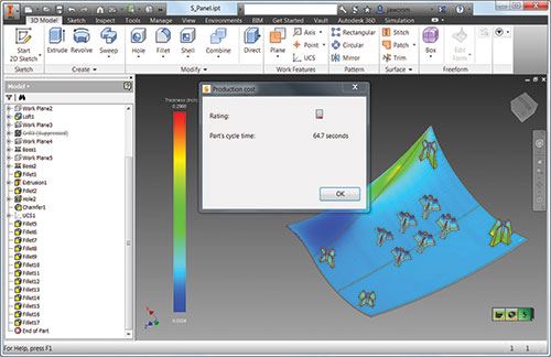
Simulation for designers. Part and tooling modifications can negatively impact project budgets and deadlines. Typically, the later these changes are made in the design-to-manufacturing process, the higher the associated costs will be. Design-for-manufacturing simulation software offers real-time “spell-checker-like” advice on plastic part design, manufacturability, cost and material impact, all within the native CAD environment during design or as a standalone solution.
This type of upfront analysis offers configurable guidelines for part design, such as acceptable thickness variation, and then relates how the design decisions will affect overall cooling time requirements and part cost.
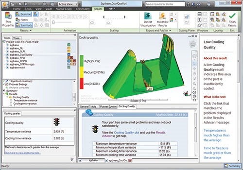
Cooling quality. Software that analyzes cooling quality identifies areas of a part that are not being cooled effectively and then enables the user to probe these areas of concern for more detailed information.
The software analysis also graphically shows regional differences in temperature and cooling time between overall part averages, and identifies part geometry modifications that can be made to avoid such differential cooling, which can contribute to part warpage. Iterative part designs, alternative process conditions and materials then can be evaluated to judge the effectiveness of any cooling improvements before details of the mold design are considered.
Steady-state cooling. This type of analysis looks at the average temperature distribution for a given molding cycle and uses the results to optimize the mold design and ensure part quality. Both part and mold temperatures are analyzed, then a cycle-averaged temperature distribution is calculated for the mold. This can help optimize various aspects of the part and mold design, including where to core out the part, cooling system layout and cycle time.
Transient cooling. Transient cooling analyses are used to simulate the change in mold temperature at different stages of the injection molding cycle. During the molding cycle, the different areas of the mold (especially those in contact with the part) will heat up and cool down around an average temperature. Typically, a mold will be hotter during the filling stage and cooler during the pressurization and cooling stages. Transient cool analyses enable you to see how the mold temperature varies over time for one stable cycle or multiple cycles, from production startup to thermal stability.
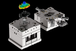
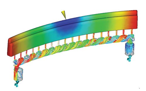
Conformal cooling. In addition to traditional tube-like cooling systems, molds can be manufactured with complex cooling shapes and cross-sections that closely follow the contours of the part. Vacuum brazing and direct metal laser sintering (DMLS) are common manufacturing techniques that can be used to create such conformal cooling channels.
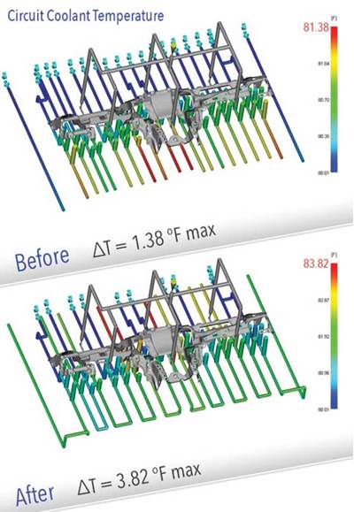
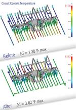
In performing conformal cooling analysis, simulation software can create 3D meshing of the entire mold and cooling system and use a computational fluids dynamics (CFD) solver to evaluate coolant flow and the corresponding mold heat transfer over the entire cycle. Such simulation can lead to cycle time savings of 20 to 40 percent compared to traditional cooling techniques and improved part quality due to reduced warpage, making it valuable for evaluating multiple cooling strategies before investments are made.
Rapid heating and cooling. Rapid mold heating and cooling techniques can be used to improve the surface quality of a part while keeping the cycle time as short as possible. This mold heat transfer optimization is accomplished by heating the mold surface above the polymer’s glass transition temperature (Tg) for the filling phase and then quickly reducing the mold temperature after fill. Simulating such rapid heating and cooling allows one to explore the best heating and cooling technology, and then couple it with timing and mold design.
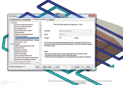
Design of experiments (DOE). DOE is a statistical engineering method that determines which variables have the greatest effect on final part quality and which have the least effect. Users input ranges of process or geometry variables, and DOE analysis shows the sensitivity of each variable and ultimately what set of conditions produce the shortest cycle time. When used early in design stages, DOE analyses can help improve part designs by guiding decisions related to the plethora of available factor combinations. This type of analysis can also be used to hone mold design details for efficiency.
Summary
Cooling is the longest component of the injection molding cycle, so optimizing cooling is important to increasing cycle efficiency and therefore increasing profit. Simulation tools can provide cooling evaluation during part design, not just during mold design, helping users make informed decisions that reduce risk downstream.
Cooling analysis is not a one-size–fits-all tool for a single user, however. It is a whole toolbox of simulation options that are custom-built for a particular user and application. To efficiently and systematically reduce costs, simulation should be integrated into a company’s entire product workflow.
Related Content
Mold Design Review: The Complete Checklist
Gerardo (Jerry) Miranda III, former global tooling manager for Oakley sunglasses, reshares his complete mold design checklist, an essential part of the product time and cost-to-market process.
Read MoreHow to Generate the Ideal Tool Path for High-Level Accuracy and Finish
When a mold builder can’t compromise part accuracy and surface finish, CAM software with specialized programming strategies is essential.
Read MoreHow to Improve Your Current Efficiency Rate
An alternative approach to taking on more EDM-intensive work when technology and personnel investment is not an option.
Read MoreTips for Tackling Mold Design, Machining, Cutting Tool and Wear Challenges
Tips for tasks ranging from reducing risk in part design and taking advantage of five-axis machining to refining cutting tool performance and reducing wear with guiding and centering systems.
Read MoreRead Next
Circuiting Done Right
Using cooling simulation to circuit your cooling lines properly.
Read MoreHow to Use Strategic Planning Tools, Data to Manage the Human Side of Business
Q&A with Marion Wells, MMT EAB member and founder of Human Asset Management.
Read MoreReasons to Use Fiber Lasers for Mold Cleaning
Fiber lasers offer a simplicity, speed, control and portability, minimizing mold cleaning risks.
Read More


.jpg;maxWidth=300;quality=90)
