Control the Process to Drive Profitability
Process control technology boosts productivity and profitability through increased throughput of good parts, reduced inspection time and dependable production schedules.
Having squeezed every second out of cycle times with increased feeds and speeds, advanced tooling and coolants, and process standardization, shops are now looking to process control to boost productivity and profitability. They have zeroed in on waste reduction, reducing costs, and increasing throughput and velocity as solutions, all of which are powered by an expanded use of process control tools. Shops are increasing good part throughput, reducing inspection requirements and establishing dependable production schedules by using laser calibration, ballbar systems, five-axis inspection and gaging tools.
Process Foundation
A solid process foundation creates machining processes that are predictable, repeatable and capable of producing conforming parts—a key component of a successful lean operation. To achieve predictable productivity, a shop must eliminate variation at its source and establish a stable operating environment with preventive controls. Consistent conditions at the start of the process set the foundation for consistent results. Machine performance assessment and calibration ensure that performance is in line with process requirements and provide baseline data for comparison and diagnostics. Using laser calibration and a ballbar to prove the capability of the machining process eliminates guesswork and unnecessary
part-handling, and increases machine uptime by reducing the need for troubleshooting.
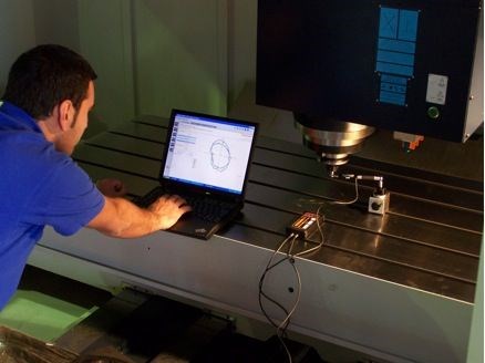
Ballbars measure extremely small variations in radius as a machine under test follows a programmed circular path around a mount on the machine table. Sensors in the ballbar capture variations in the radius and transmit them wirelessly to a computer where software records the deviations, compares them to a perfect circle and analyzes the results. Ballbar diagnostics can also determine machine squareness as a prerequisite for analyzing backlash and reversal spikes. Once the level is set, reversal spikes, backlash and scaling mismatch are diagnosed and remedied using data that compares optimal machine settings to the ballbar test results. The comparative data that is generated also can be used to qualify metrology and time maintenance decisions, to implement continuous improvement techniques such as total productive maintenance (TPM) and statistical process control (SPC), and even to forecast machine life. By implementing a frequent-testing program, experienced ballbar users can monitor everything from linear-guide and ballscrew wear to vibration analysis. Using the data, operators can make adjustments, schedule downtime and maintain part accuracy as machine components wear out, rather than depend on the quality of finished parts to determine machine capability.
The benefits of a good process foundation include increased machine availability, better machine accuracy and repeatability, and less part-to-part variation and scrap/rework. A good process also provides a foundation for automated process setting.
Automated Setting
Building on the stability introduced by a solid process foundation, process setting then prepares for machining by automating manual processes to eliminate time-consuming setup activities and human error. It also reduces setting times by as much as 90 percent by eliminating setup errors. Predictable sources of variation, for example, part location, tool and offset size, or anything that could cause a non-conforming first part, are taken out of play with proper machine, probe, part and tool settings.
Machine setting uses on-machine probing to measure and eliminate errors caused by thermal drift between key moving parts, such as the spindle and bed. Uncorrected machine errors can be a dominant factor in process non-conformance and can cause extended setup times if the effects are confused with other sources of process variation.
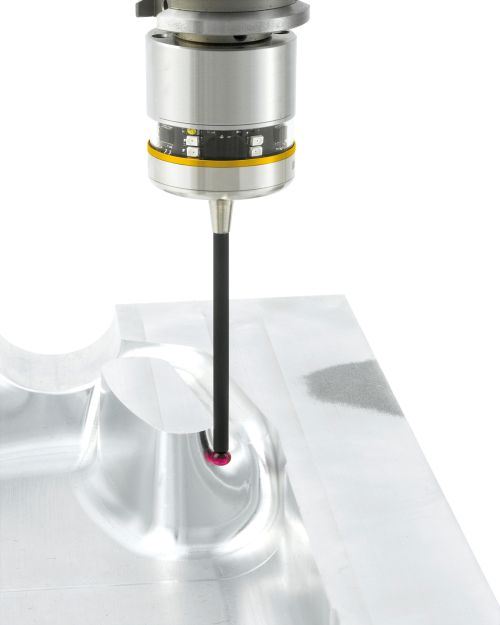
Probe setting involves datuming the probe so that it can measure accurately on the machine. The stylus size and position are measured using a datum sphere or ring gage. Or, in the case of tool-setting probes, a tool arbor is used to establish the position of the stylus. Regular probe calibration ensures other measurements on the machine remain reliable.
Part setting uses a touch probe to establish workpiece location and orientation, and to align the machining program by identifying datum positions and angles, and automatically updating coordinates. It eliminates the need for human intervention, and can also reduce or eliminate the need for complex, precision fixturing as the probe finds the part. Operator miscalculations and improper input of workpiece or tool offset data to the control are the top causes of machine crashes, scrap/rework and tool breakage. Automated part setting allows companies to take advantage of the precision and repeatability of their machines with fast, accurate, repeatable measurements. Automatic updates of tools and work offsets also eliminate calculation and keying errors. Automating part setting and automatically updating fixture offsets to the control can reduce setting time by 95 percent, saving 30 hours per batch of parts.
Tool setting measures tool length from the spindle gage line. This establishes height offset and confirms that the length is within specified tolerance. It also establishes the tool size offset by measuring tool diameter while the tool is rotating, which eliminates errors caused by runout and variation in insert height. All tool-setting information is stored in the CNC. Tool setting is more repeatable than manual measurement, and a suite of tools can be set in minutes without “cut-and-measure” trial cuts. In addition, probing software updates tool offsets automatically, which prevents human error and reduces tool and/or part damage. Broken-tool detection functions allow in-cycle checks for broken and/or chipped tool edges, as well as tool position to ensure pullout has not occurred and to prevent scrap/rework.
Knowing Parts are Correct
Once process control and a calibrated machine are established, shops can measure parts directly on the machine. In-process control monitors and documents operations using probes to deliver intelligent feedback to the process, and to address variables such as temperature and tool wear. No operator intervention is needed. It can also perform quick in-process measurements of critical part features. In-process control can increase machine performance as much as 98 percent, as unplanned stoppages and time waiting for operators is reduced by automated in-cycle feedback. Part quality rises and inherent variation is managed at the source.
Post-process monitoring is often done offline and ensures that both the process and part are checked against specifications. Most shops perform post-process monitoring by using machine tool probes, handheld or comparative gages, articulating arms, and coordinate measuring machines (CMM). Post-process measurement with the part in the fixture makes the most sense for large, high-value parts. CMM-style checks, including geometric dimensioning and tolerancing (GD&T), can also be performed on the machine tool, however they will be less precise and traceable than those done on a CMM, where measurement cycles may be shorter because of technologies like five-axis scanning. CMMs equipped for five-axis scanning will also be faster and more comprehensive in measuring complex shapes. In addition, CMM measurement results and point data are easily stored for long-term traceability.
Shops that understand the benefits of probing can save days, not just seconds, in setup time. They can also eliminate machine downtime through automated process feedback directly to the machine tool. Without making any fundamental changes to the machining process, adopting advanced measurement and inspection concepts can allow shops to bring stability to delivery schedules, enabling shorter manufacturing lead times and lower operating costs.
Related Content
5 Hot Runner Tips for Moldmakers and Molders
Best practices for initial hot runner tryouts and effective preventive maintenance.
Read MoreThe Ins and Outs of Hot Runner Temperature Control
A training checklist that explains the why and how of proper hot runner temperature control and system management.
Read MoreLine Width vs. Depth Ratio in Laser Engraving
A laser does not produce 90-degree sidewalls. It requires a certain amount of draft in order to produce the required pattern.
Read MoreRead Next
Streamlining Setups at Seescan
In addition to new equipment, this captive shop’s transformation involved implementing strategies to make the most of existing resources.
Read MoreAre You a Moldmaker Considering 3D Printing? Consider the 3D Printing Workshop at NPE2024
Presentations will cover 3D printing for mold tooling, material innovation, product development, bridge production and full-scale, high-volume additive manufacturing.
Read MoreReasons to Use Fiber Lasers for Mold Cleaning
Fiber lasers offer a simplicity, speed, control and portability, minimizing mold cleaning risks.
Read More
