Across the Bench: Troubleshooting Defects: Part I
Using analytical skills based on historical mold performance and maintenance requirements, combined with mold and part defect data determines probable causes and corrective actions.
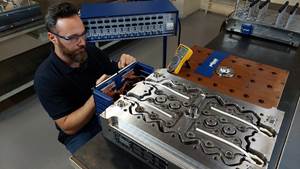
| We left off last month with our mold on the bench, the "B" side disassembled and all plates separated, standing and braced in the vertical position. We will now separate the "A" side cavity plate from the hot manifold probe plate to complete the disassembly stage and move on to troubleshooting.
"A" Side (Hot Runner) DisassemblyThe "A" side of the mold is a typical off-the-shelf (angled shut-off) valve gated, pneumatically actuated hot runner system, bolted to the "A" side cavity plate. The cavities in the plate are cooled in typical fashion-i.e., water lines bored through the plate directing the water flow around the o-ringed cavity inserts and held in place with a retaining plate. Before beginning disassembly procedures of a hot runner system, all the plates should be cooled to room temperature to prevent possible damage. Check your systems manual for specific instructions and temperature guidelines. As a general rule, individual plate temperatures that vary more than 50 degrees may cause critical tooling such as probe seals, valve pin tips and cavity gates to wear prematurely or suffer galling damage when separating due to misalignment between the plates from heat expansion. Separate the "A" plates in the same manner as the "B" side. Support the cavity plate with the overhead hoist as you carefully remove the cavity plate and expose the heater probes. Brace the cavity plate before you unhook it from the chain hoist. The mold is now disassembled and in a position that allows easy access to troubleshoot, clean, inspect and replace tooling if necessary, from both the "A" and "B" sides.
Troubleshooting Mold and Part DefectsLike the three other aspects of a typical C/R of a mold (disassembly, cleaning and assembly) there is usually more than one way to approach the task of troubleshooting and correcting defects. The type of business (custom or proprietary), in-house fabrication capability, parts produced (automotive or medical, high volume or low) and mold type can influence specific aspects of troubleshooting and maintenance practices. But regardless of these differences, the ability of your repair technicians to quickly and accurately answer the first three questions on the Troubleshooting Flowchart (see Figure 1) will ultimately describe your level of maintenance efficiency. If your method of tracking past mold or part issues is cumbersome for repair technicians, then use of important historical data will not happen, so proactive maintenance will not take place. Firefighting problems and freelancing repairs becomes the accepted practice. Every technician doing his own thing and choosing to wing it does not promote repair consistency or mold reliability. The two most commonly used methods are: 1. Dimensional tooling inspection to correct flash-Measure the tooling in the area creating the flash. If it is worn past the specified print tolerances, replace it. Cut and dried. Advantages: Speed-Troubleshooting is now regulated to installing new or reworked tooling. Disadvantages: Inaccurate repairs-Replacing tooling simply because it is slightly under print tolerance does not guarantee an accurate repair has been made, or that the tooling won't quickly wear out again in the same area. Many factors contribute to the decision to replace tooling such as position history, resin issues, process and press conditions such as clamping techniques and platen parallelism, cooling, heating, fill characteristics, plate alignment and condition. (See An Expensive Alternative Table at end of article). 2. Data-based troubleshooting-Use analytical skills based on historical mold performance and maintenance requirements combined with mold and part defect data to determine probable causes and corrective actions (see Figure 1). Advantages: Proactive maintenance-Wear is better forecast allowing cyclical cleaning and tooling replacement standards to be set and proactive measures implemented and monitored. Troubleshooting becomes easier and more accurate while tooling and labor costs decrease. Disadvantage:
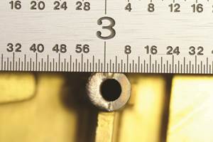
Troubleshooting Flash Between Parallel Tooling Shut-offs: (Data-Based)1. Examine the flash on the blocked-off part. Measure the thickness of the flash if possible to get an idea of what the tooling should reflect. Flash over 0.005 thick can point to tooling stack or preload issues. 2. Remove the suspect tooling from the mold and orient the flash on the part to the tooling using the cavity I.D. location, gate location or part configuration as a guide to see exactly where the flash is occurring. 3. Examine the tooling for obvious signs of wear or hobbing at the flash point. If the flash or suspect area of the tooling is small, use a microscope to magnify the view. Mark the tooling beside the suspect area with a felt pen. 4. Use a dial test indicator (0.0001 resolution) to measure the depth of the hobbing or worn surface. Use your experience and historical data with the tooling and resin to make accurate decisions as to which tooling needs to be replaced, and which is still good. Troubleshooting Flash Between Between Cores, Sleeves, Bushings, Angled Shut-offs1. Examine the flash on the blocked-off part, and orient it to the tooling. 2. When checking for this type of tooling wear, a quick and accurate procedure is to interchange new tooling with old, examining the different fits under a microscope. Be sure to orient the tooling as it runs in the mold and pay attention to any track marks on the tooling. This will allow you to feel the movement and see the clearance (wear) between the tooling as you swap back and forth. If you want to measure the movement, this can be done by setting up a dial test indicator on a granite surface plate perpendicular to the movement you want to measure. Be sure to stone off any burrs, dings or surface irregularities that prohibit the tooling from setting flat on the surface plate. 3. Angled surfaces should be checked on a sine plate with the dial test indicator for flatness and hobbed areas. 4. Once a determination is made as to what tooling will be replaced, grind or etch the mold position number on the new tooling and reinstall. These steps are repeated until all defects are corrected. Next month's Across the Bench will address disassembling and troubleshooting the defects in the manifold.
|
Related Content
How to Use Scientific Maintenance for More Accurate Mold and Part Troubleshooting
Discover how adopting scientific maintenance approaches helps improve mold lifespan, minimize failures, and optimize production outcomes.
Read MoreLaser Welding Versus Micro Welding
The latest battle in finely detailed restoration/repair of mold materials.
Read MorePrecision Meets Innovation at IMTS 2024
After attending IMTS, it's clear that the integration of advanced technologies is ready to enhance precision, efficiency and automation in mold manufacturing processes. It’s a massive event, so here’s a glimpse of what the MMT team experienced firsthand.
Read More5 Hot Runner Tips for Moldmakers and Molders
Best practices for initial hot runner tryouts and effective preventive maintenance.
Read MoreRead Next
How to Use Strategic Planning Tools, Data to Manage the Human Side of Business
Q&A with Marion Wells, MMT EAB member and founder of Human Asset Management.
Read MoreHow to Use Continuing Education to Remain Competitive in Moldmaking
Continued training helps moldmakers make tooling decisions and properly use the latest cutting tool to efficiently machine high-quality molds.
Read More


