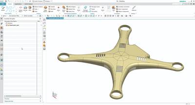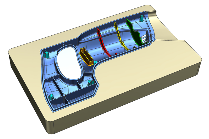
CAD tools are used to decompose the solid body into individual design features for additive manufacturing programming. All photo credit: Siemens Digital Industries Software
Additive manufacturing (AM) of metals is gaining market acceptance with specific use cases, including some workflow examples in moldmaking such as building up components with conformal cooling channels, printing expensive metals for less waste or performing repair work to extend the life of production molds.
When it comes to the "big picture" view of AM, there are two approaches to moving the deposition head: flatbed (or planar) and multi-axis. Flatbed is the most common method used on printers ranging from inexpensive home 3D printers to large industrial metal laser sintering systems. When using the flatbed approach, parts are nested in a work envelope, and slicing is always planar — usually perpendicular to the Z-axis — and completed in that one direction.
The multi-axis approach deposits material in directions, compared to just one vector or direction. The print head of these systems is mounted inside a 5-axis CNC machine or mounted onto a robot. They are referred to as hybrid multi-axis additive machines and can perform both additive and subtractive operations.
Programming software for multi-axis AM can often be found as an add-on or option to existing 5-axis CAM systems because programming multi-axis AM more closely parallels programming 5-axis milling operations than it does flatbed slicing. Although a fair amount of overlap in software options exists between multi-axis milling and additive, there are unique features for each manufacturing method.
Mold builders can use both flatbed and multi-axis AM, but multi-axis is often used to coat molds, repair molds, or build mold components to reduce material waste (when using exotic alloys). CAD functionality in multi-axis AM, used for getting a part ready to program is as important as the actual programming operations. Since many mold builders use subtractive operations on additively-manufactured parts, an integrated CAD/CAM/AM solution can be beneficial.
Keep in mind that creating multi-axis additive post-processors is just as technical as creating five-axis milling post processors — possibly more technical.
Fundamental Multi-Axis AM Programming Workflow
Let's take a look at five key aspects of a basic workflow for programming a multi-axis AM part along with the necessary CAD/CAM/AM system tools.
-
Part Decomposition
Decomposing a part is the process of taking the solid body to be programmed and splitting (decomposing) it into individual features or individual solid bodies based on how each feature will be programmed and printed. This process uses CAD design tools for manipulating the original solid body.
In one sense, multi-axis AM relies on CAD tools to prepare parts more than 5-axis machining. It is not uncommon to spend a fair amount of time performing CAD design functions before programming any additive operations. The design (CAD) tools and programming (CAM and AM) tools in the same software package and user interface avoid the need to swap software multiple times to program, simplifying the task.
For example, splitting larger solid bodies into individual bodies is key to part decomposition, and this entails splitting by a plane, a cylinder, or a face. Having CAD decomposition tools with multiple options for defining planes and cylinders makes this job more manageable.
Strong surface functions also ease part decomposition. Face extraction, creation and modification functionality are critical for decomposing parts that are not defined by planes and cylinders, such as components typically machined for a mold. For instance, mold builders often split solid features based on an extracted face, so working with surfaces that are offset, extended, or sewn together to create custom foundation faces or thin-wall sections allow them to program the parts exactly how they prefer.
-
Part Arrangement and Machine Kinematics
This process involves digitally placing a part and the necessary build plate into the machine to verify that you can meet the size and angle requirements. When 5-axis CNC milling, gravity allows the chips to fall, but when using AM, gravity works against you. Understanding how to use machine angles and kinematics is essential to ensure you have enough room and movement to build the part.
-
Part Programming
Many part requirements or features are necessary to produce higher quality parts. Here are eight specific part requirements or features to consider—some of which are common to both additive and subtractive manufacturing and others unique to AM.
Actual 5-axis movement: A mold builder using AM can produce higher quality builds on complex parts when the deposition head moves with full 5-axis motion. The orientation of the nozzle and laser to the part is more critical when depositing material than when milling with a ball nose cutter.
For example, sidewalls with either positive or back draft benefit from 5-axis movements on the outside wall. This is especially true with blown powder and laser processes because you align the laser and powder to the drafted wall instead of allowing gravity to influence the process.
When coating the top of a part—such as depositing a single layer of a harder material onto a mold surface—multi-axis moves will allow more consistent layer thickness.
Buildup, thin-wall and coating operations: For additive manufacturing, one uses buildup operations to create layers and fill solid bodies, building up larger parts. Thin-wall operations create just one bead, using a face or sheet body as a guide. Coating operations coat material onto the top of a part. Both are useful for building parts but especially helpful for repair functionality.
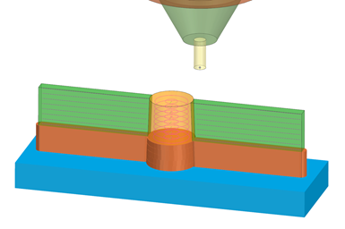
When different operations are used to program a part, merge automatically resorts the layers to print in the correct order.
Merging operations: This requirement is more unique to AM than to milling. For example, imagine creating an operation on a body with one set of parameters and a second operation on another body with different parameters; however, you want to build the two bodies simultaneously to avoid collisions during the build process or join two different materials.
Merge functions allow the user to merge multiple operations, each with different parameters, and then automatically re-sort the individual layers of each operation, completing the build. Analogous to shuffling two decks of cards together. Ideally, merge functions should not require a lot of manual sorting.
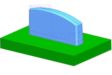
By staggering start points per layer, you can reduce potential overburn or over-deposition at one spot.
Staggering start points: The start points of the profiles often align with previous levels at each depth when milling contours use multiple levels. However, start point alignment can be a disadvantage with metal AM.
With AM, one must always take into consideration adding too much heat or metal into one area. If the start points of every layer are in alignment, it may overbuild material at that point, creating an undesirable finished part. The ability to stagger the start points from layer to layer helps spread the heat around and eliminates the possibility of overbuilding that one point.
User-defined events: These are events or commands added by the users to the calculated output and can be unique to AM. For example, with blown powder applications, a user may wish to input a command to blow excess powder away at some time interval. Other users may want to change a machine parameter just before the end of a deposition string to increase the output quality of the build.
Automatically adding user-defined events offers finer control within the operation and can be unique to a specific workflow or deposition technology.
Corner handling: Sharp corners can also cause too much heat and build up in one area
For example, the speed at the tip of a tool can be very slow compared to the rest of the machine when using a large 5-axis kinematic movement in a sharp corner. This can cause an overbuild situation as well.
Using optional corner handling functionality gives the user options to modify or even turn off the deposition in the corner for a second, reducing the possibility of overbuilding.
Spring passes: In subtractive machining, spring passes are used when an extra milling pass on the same profile is necessary to account for any deflection in the tool or springiness in the material.
The gravity and draft angles associated with AM result in finish passes that may not always deposit enough material. Spring passes in AM are the same as in subtractive—an extra pass on the finish profile. This can be automatically applied all the time, or applied based on draft wall conditions to ensure a complete build of a part's sidewalls.
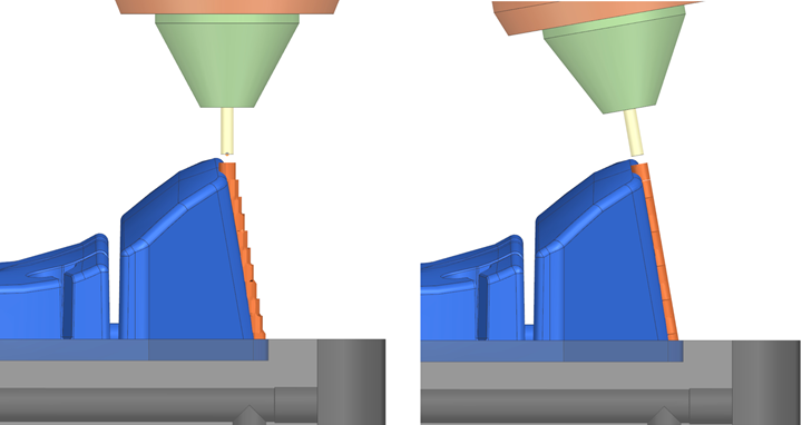
Five-axis movements on sloped geometry can create more accurate walls, versus 3-axis operations.
Five-axis traverses: One goal of 5-axis machining is to limit non-cutting moves (or air travel) to gain efficiency. However, in AM, you may want the opposite. The user may want to move the deposition head around more to spread the heat during deposition around and prevent a single area from absorbing too much.
Merging different operations per level will force the tool to move back and forth more often, which has the benefit of spreading the heat around.

Optimize approach, retract and traverse motions using smooth 5-axis motions.
Five-axis traverse options such as plane, box, cylinder and sphere (with a smooth approach and retract movements) allow the machine to perform these movements more smoothly and efficiently. Here is where an integrated 5-axis CAM system can lend existing functionality to multi-axis AM operations.
Ideally, in hybrid additive/subtractive environments, the same additive simulation model and also verify any subtractive operations in the workflow.
-
Program Verification
Verifying the program using machine simulation, one can see the deposition process and visually see if there are issues with excessive kinematic movement, possible collisions, or large voids. This will simulate the beads, in the same order, on the digital twin as they would be on the machine. Ideally, in hybrid additive/subtractive environments, the same additive simulation model and also verify any subtractive operations in the workflow.
-
Post Processing
After you decompose a part with CAD tools, mount it to a machine, program your additive (and subtractive) operations, and verify every post-processing step. Keep in mind that creating multi-axis additive post-processors is just as technical as creating 5-axis milling post processors—possibly more technical. To achieve a complete build, it is crucial to have a fully functional post-processor that can correctly interpret movements, deposition commands and user-defined events.
Related Content
Maintaining a Wire EDM Machine
To achieve the ultimate capability and level of productivity from your wire EDM on a consistent, repeatable and reliable basis, regular maintenance is a required task.
Read MoreLaser Welding Versus Micro Welding
The latest battle in finely detailed restoration/repair of mold materials.
Read MoreThe Ins and Outs of Hot Runner Temperature Control
A training checklist that explains the why and how of proper hot runner temperature control and system management.
Read MoreRevisiting Some Hot Runner Fundamentals
What exactly does a hot runner do? If you’ve been in the injection molding industry for any length of time, you might think the answer is obvious, but it is not.
Read MoreRead Next
Five Ways to Tackle Tough Mold Design Tasks with Digitalization
Transform static 3D designs into animated 4D designs that simulate motion and interaction of complete mold systems to improve design workflow.
Read MoreBringing Topology Optimization to Injection Molds
Topology optimization and an integrated software solution help a mold builder produce an injection mold with 50-percent less mass, permitting faster machine motion for 30-percent faster cycle time.
Read MoreHow to Pre-Estimate Tooling Costs
The right costing software can help to improve mold quoting and production.
Read More

.JPG;maxWidth=150;quality=70)



.JPG;maxWidth=400;quality=70)
