Upgraded CAM Software Tools Support 3D Mold Embossments
The BobART add-on module included in BobCADCAM’s V35 software is a powerful tool that enables users to add text and logos to existing 3D models.

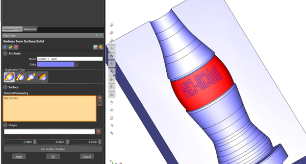
Emboss for surface/solid in BobArt. Photo Credit: BobCAD-CAM
Creating 3D embossments for molds from 2D text or images has been simplified via BobART, an add-on module of BobCAD-CAM V35, a software that supports two- to five-axis machine and controller configurations popular with moldmakers. Using BobART, moldmakers are able to customize tooling, adding 2D or 3D text, shapes, textures and more to existing 3D models. Recent updates improve workflow while adding flexibility and functionality — such as updating the 3D model as users make adjustments — with a complete UI upgrade.
BobArt is a separate tree in the BobCAD-CAM software that can be used in standalone BobCAD, BobCAM for SolidWorks and BobCAM for Rhino. The BobART tree is used to load images, vectorize image files and create embossed models with curvature. Users are able to create embosses by simply using 2D lines, arcs and splines. Curvature can also be added to the embosses while keeping the extrusion projected down the Z-axis. This enables users to use a three-axis operation to create the toolpath without having any surfaces that would need undercutting or five-axis machining. The new workflow includes an “Apply” button to preview the changes to embossments directly inside the feature, making updates easier for the design process.
BobCAD-CAM also provides toolpath operations popular for hard milling, rest machining and finishing operations. Using rest finishing, users can target material left behind from previous cutters, finishing inside corners and smaller radius sections of tooling. Details for which toolpath options come with what packages can be viewed here.
Additional features, functions, modules and enhancements offered in V35 can be found here.
Related Content
-
How to Improve Your Current Efficiency Rate
An alternative approach to taking on more EDM-intensive work when technology and personnel investment is not an option.
-
It Starts With the Part: A Plastic Part Checklist Ensures Good Mold Design
All successful mold build projects start with examining the part to be molded to ensure it is moldable and will meet the customers' production objectives.
-
How to Select a Mold Temperature Controller
White paper shares how cooling channel analysis, which collects maximum pressure drop, total flow rate and heat dissipation, eases the performance evaluation of mold temperature controllers.


