Software Update Gives Users Sharper View of the Machining Process
CGTech announces the latest release of VERICUT software, Version 9.0. Vericut CNC machine simulation, verification and optimization software simulates all types of CNC machining, additive and hybrid manufacturing processes.
Share
Read Next

CGTech announces the latest release of VERICUT software, Version 9.0. Vericut CNC machine simulation, verification and optimization software simulates all types of CNC machining, additive and hybrid manufacturing processes. The software operates independently but can also be integrated with leading CAM systems. Version 9.0 features several enhancements designed to increase power and improve efficiency, including a new graphics engine. Users will experience sharper, clearer and more realistic views of machines and the machining process. Hundreds of customer-driven enhancements and software change requests were also completed.
The software’s enhanced image quality makes it easier to spot problems and imperfections in machined parts. Switch seamlessly between Workpiece, Machine or Profile views, or combine them in a variety of view layouts. Any of the software’s major functions can be used in any view, which streamlines the verification effort and increases productivity.
Use Force “Analyze”, without any prior configuration, to spot potentially dangerous machining conditions or identify underutilized tools. Force Charts has a new “Fill Comparison” option to help visualize the changes made by Force optimization to feedrates and chip loads. Appearance settings accompany the “Color” option for components and models, and can be used to add realism to objects in simulations. Machined parts look more lifelike and identification of errors or incorrect cuts has become easier. New features are available to display the Design part embedded in translucent Stock, and show AUTO-DIFF Gouge or Excess errors in relation to the Design part or cut stock model.
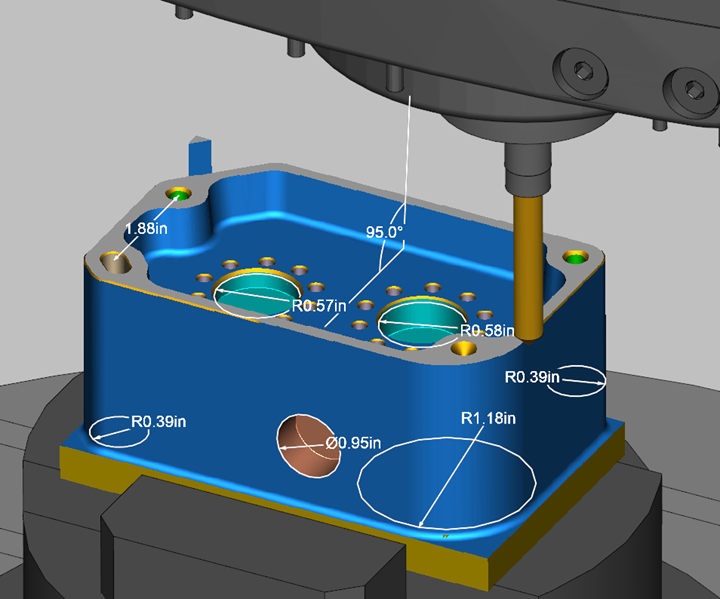
X-Caliper has several new measurements and features that provide greater control over how measurements (dimensions) are shown. Images with dimensions can be printed, saved to an image file, or utilized in Setup Plans. A new Setup Plan capability can create images from the simulation with dimensions or notes that help others understand the manufacturing process. Setup Plans are easily incorporated in VERICUT’s reports to document operation setups, or how machined parts should look at various stages. The new Multi Tool Station tool component has been added in Tool Manager, enabling users to setup an apparatus that holds multiple tools, attached to a single turret station. Tool Change List panel is enhanced with capabilities to graphically setup tools on turrets, in tool chains, define orientations for “Flash” multi-function tools and more. The Reviewer application is powered by the same enhanced graphics engine featured in Vericut Verification. The Section window is easier to use with dynamic section plane locations and angle adjustments.
Related Content
-
Tolerancing in Mold Design, Part 1: Understanding the Issues of Conventional Bilateral Tolerancing
Mold designers must understand the location, orientation and form limitations of conventional tolerancing before changing to another dimensioning system.
-
Four Micro Tooling Considerations
Issues involving gating, ejection, mold splits and direction of pull are of special concern when it comes to micro tooling.
-
How to Improve Your Current Efficiency Rate
An alternative approach to taking on more EDM-intensive work when technology and personnel investment is not an option.


