Mold and Die Focused Software Tackles Process Optimization, Usability, New Technology
Cimatron’s CAD/CAM version 16 release enable toolmakers to deliver higher quality tools faster, easier and more efficiently.
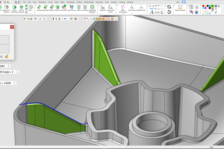
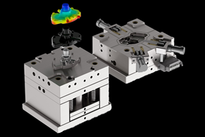
CAD enhancements include the ability to create structural ribs from either a 2D or 3D contour. Photo Credit, all images: Cimatron
Cimatron, a CAD/CAM software supplier for the mold and die industry, has announced the release of its mold and die focused product, Cimatron V16. After an intensive period of industrial beta testing, Cimatron V16 is now available for general distribution.
Version 16 is said to be a substantial release introducing many new features in all areas of the product including a clean new UI and increased automation for faster mold design, electrode creation and NC programming. In addition, the continued emphasis on solutions for toolmakers includes powerful functionality for die addendum surfaces, mesh manipulation and drafting detailing, according to Cimatron.
CAD enhancements include the ability to create structural ribs from either a 2D or 3D contour, with draft angle and flat or rounded tops. Working with mesh models has also been improved with new capabilities for closing open areas, curvature mapping and the option to define local mesh areas where it is possible to set finer mesh tolerances to describe more intricate model details.
User efficiency continues to be Cimatron’s focus with the process workflow having been improved in several areas including batch printing with support for shaded views, dynamic triad dragging, expanded bill of materials (BOM) support for assembly structures and extended preferences control with the ability to search and reset.
For moldmakers, several new mold layout types are now available including smart mirror and array with the setup wizard controlling the parameters for layout sub-type, rotations and cavity distances. In addition, a feature for automated ejector locking has been added that detects which ejectors need to be locked and the type of lock required to prevent their rotation in the ejector plate, and then modifies the head to create the appropriate pocket in the ejector plate.
Surface extension capabilities have been enhanced for both mold and die makers with a tangent skin extension function which Cimatron says provides the ability to automatically extend surface edges to aid the construction of core and cavity parting faces. The die design extend faces has also been improved to better manage internal corner conditions that would create overlapping face extensions. In this scenario, it is now possible to replace the affected area with a smooth continuous patch surface.
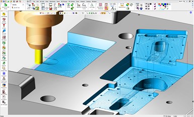
VoluMill pocketing can now be applied to multiple open and closed pockets of differing heights and depths as a one-step routine and single NC operation.
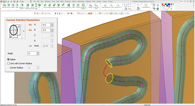
Conformal cooling can benefit all types of molded parts and Cimatron 16 now offers more automated methods for optimized cooling path generation. Also, a new virtual volume function lets the user limit a cooling circuit to a portion of the shape volume and avoid sections that do not require a cooling channel. Further enhancements include a new optimized curvature function that highlights areas where a cooling channel cannot be created, such as a curve radius smaller than the channel diameter, providing the user with point-and-click controls to correct the channel path.
Electrode design is a critical part of the mold production process and Cimatron 16 brings a number of developments. These include the ability to apply surface-based templates for multi-lump electrodes, EDM setup enhancements for material support with connected manufacturing attributes and support for System 3R holders. For the production process, machining electrodes is reportedly easier to control as users can now specify the electrode burning stage from rough through to polishing directly within the NC setup. All relevant machining parameters will be applied automatically according to the EDM setup with a new mechanism to automatically create the NC files.
Cimatron 16 represents another release with major CAM developments to support NC automation. Three-axis rough and volume pocketing now supports the automatic selection of multiple cutters of different lengths for the optimum cutting sequence by splitting the toolpath into multiple operations based on cutting length. This efficiency feature for rough parallel, rough spiral and volume pocket results in better tool selection, reduced tool vibration, extended tool life and faster cutting speeds.
VoluMill pocketing can now be applied to multiple open and closed pockets of differing heights and depths as a one-step routine and single NC operation. Other 2.5-axis operations include a new capability in the slotting procedure that uses pre-drilled holes for safe material entry and to speed up machining with optimum toolpath movement at each level. Further efficiency gains can be achieved with multiaxis drilling routines that consider the real stock model instead of the geometry bounding box. This creates a starting point closer to the stock for a safer, faster machining cycle.
New optimized curvature functionality highlights areas where a cooling channel cannot be created, providing the user with point-and-click controls to correct the channel path.
For three-axis machining, the geodesic morph and geodesic 3D-step procedures which generate constant surface stepover toolpath for high-quality surface finishing are now available for all NC users.
Five-axis deburring has been extended to support extra cutter types including end mill, sphere mill, lollipop mill, taper mill and chamfer mill. Importantly, the new multiple cuts feature enables the user to create more than one cut along a sharp edge to generate a chamfer or fillet shape either by constant width or by constant depth for a chamfer, or by constant width or constant radius for a fillet.
Other CAM developments include automatic arc for lead-in/lead-out, additional surface path options for milling, better handling of undercuts for five-axis roughing, and the ability to import cutters and holders directly from external data formats such as STEP, IGES and STL, as well as Cimatron solid files (ELT). The system automatically identifies the shapes and creates their respective representation in the tooling database table. In addition, the ability to copy and paste geometric data between procedures enables users to efficiently input data between machining procedures, or to multiple procedures, for easy and error-free programming.
Related Content
How to Manage Wall Thickness Changes in Your Mold Design
To ensure even filling and cooling, consider wall section transitions, corners and fillets, ribs and bosses, lip and rim designs and CAE flow simulation software.
Read MoreTolerancing in Mold Design, Part 1: Understanding the Issues of Conventional Bilateral Tolerancing
Mold designers must understand the location, orientation and form limitations of conventional tolerancing before changing to another dimensioning system.
Read MoreTips for Tackling Mold Design, Machining, Cutting Tool and Wear Challenges
Tips for tasks ranging from reducing risk in part design and taking advantage of five-axis machining to refining cutting tool performance and reducing wear with guiding and centering systems.
Read MoreHow to Analyze and Optimize Cutting Conditions to Reduce Cycle Time
Plastic injection mold design and manufacturing company puts NC program optimization software module to the test. The results were surprising.
Read MoreRead Next
How to Use Continuing Education to Remain Competitive in Moldmaking
Continued training helps moldmakers make tooling decisions and properly use the latest cutting tool to efficiently machine high-quality molds.
Read MoreHow to Use Strategic Planning Tools, Data to Manage the Human Side of Business
Q&A with Marion Wells, MMT EAB member and founder of Human Asset Management.
Read MoreReasons to Use Fiber Lasers for Mold Cleaning
Fiber lasers offer a simplicity, speed, control and portability, minimizing mold cleaning risks.
Read More


