Achieving Cavity Balance: Another Factor for Success
A look at good and bad cavity layouts and runner designs.
One of the basic requirements for successfully molded parts is that we must have cavity balance in order to achieve process robustness and fast cycle times that are necessary to be profitable in today's competitive, global market. In this article we will take a basic look at good and bad cavity layouts and runner designs.
Good cavity and runner design is crucial in order to achieve a balanced fill where all cavities fill at the same time with the same shear rate. If some fill prior to others, pack and hold will not have the same influence on all cavities and dimensions will be different. If this is the case, band-aids will need to be applied to the process in order to achieve the level of quality required. This can be done by trying to manipulate the injection speeds, over packing most cavities as well as many other adjustments. This will result in a very small process window that will not encompass all the normal variations that are expected. Needless to say, the process will never be optimized or as profitable as it could have been.
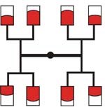
We will start with a traditional eight-cavity layout as seen in Figure 1. With this design the inner four cavities will generally fill first due to orientation stress from the inside square corners. Related to plastic flow, tee intersections cause shear imbalance in the runner. This phenomenon will cause the plastic to continue to turn in the same direction when the next junction is reached, thus filling the inside cavities first. When the inside cavities are full, flow stops while the outside cavities continue filling. During this secondary filling of the outside cavities, the inner cavities' plastic is cooling and unorienting, raising the viscosity in the inner cavities. This allows more influence in the outside cavities during pack and hold, which provides the potential for the outside cavities' parts to be larger. The more the fill imbalance the more problematic the mold will become.
A better choice would be to use a runner as shown in Figure 2. The cavities have the opportunity to fill at nearly the same rate and the orientation stress developed will be nearly the same.
It is important to use large radii in the runner layout. This will reduce the shear imbalance and allows even filling.
An area that should not be overlooked is the cold slug well. It must be slightly larger in diameter than the largest sprue diameter and 1.5 to two times that diameter in depth (see Figure 3).
This will give us the best opportunity to catch partially cooled material that develops at the end of the nozzle between cycles. This is a lot like playing baseball; you want to catch the ball in the catcher's mitt every time or the game could be a loss. So, we want to catch the one and only cold slug in the well every time so as not to affect the plastic flow in the runners gates. Not catching it would cause a roaming balance issue from cavity to cavity, creating another variable.
There are three main runner shapes that are used (as shown in Figure 4): (1) full round (2) half round and (3) trapezoidal with each one having certain qualities and performances that may be needed to support delivery of the plastic to each cavity.
The full round is probably the most difficult to machine, as it must be machined into both halves of the mold, which must match perfectly. If they do not match the potential for affecting shear rates, the addition of square corners and sharp edges will adversely affect the plastic flow. A properly machined round runner has the best theoretical flow of the three runner shapes. Half round is the easiest to machine, but it does not have the most robust flow characteristics. The trapezoid will have better flow than the half round and is relatively easy to machine.
Adding a radius to the bottom, as shown, makes it an optimum solution. One other benefit is that when a trapezoidal runner cools it typically sinks on the flat sides, allowing for superior release. This is a good choice for materials that dictate a large runner, such as PVC. Remember, you must get runner release in order to achieve those great cycle times. Many times poor runner design limits the cycle time.
Now that we have established a cavity layout, type of runner and shape, we need to select the gate type. Always consult the design guide for the gate type and size. Any gates that are left attached to the parts may require a second operation to trim the parts, which add cost to the final product. Gates such as sub gates detach themselves during ejection, eliminating that secondary operation.
Next we have to determine the size of the gates and runners. In an optimized system we want to have the smallest runner volume and still be able to fill and pack each cavity the same. Gate size should be as small as possible without introducing shear rates above that known to cause degradation. Filled materials or those that are shear sensitive require larger gates. Contrary to popular opinion, there are normally not large pressure losses across small gates. Our instrumented molds have proven this time after time. Small gates cause shear, which untangles long molecules and lowers viscosity. A rule of thumb is that gates are 40 to 60 percent of part thickness. Gate sizes and types are many times determined by part aesthetics.
In order to minimize pressure losses we would like to maintain the same shear rates in all runners. Working from the part to the sprue bushing we will now establish the first runner size, which will be the diameter of the wall thickness, in this case .100". When we come to a junction where plastic branches we must increase the runner size by 25 percent to .125". Each time we branch to another runner level we again increase the runner size by 25 percent (to .156” in this case) until we reach the sprue bushing (see Figure 5). The 25 percent increase, as described, will achieve the same shear rates above and below the runner branches. The theoretical value is 26 percent, but 25 percent is close enough.
A word of caution—if the runner has long flow lengths we may need to increase its diameter as much as another 25 percent. This can be validated during the rigorous mold tryout by doing a pressure loss study. Remember that it is easier to open a runner up rather than make it smaller. Runner and gate optimization also can be achieved using flow analysis software.
Doing your homework before the runner has been cut may save problems with trying to get a mold to fill correctly without hindering the machine's capabilities. This gives you the best chance of delivering the plastic to each cavity at the same time with the same shear rates and the same packability.
When mold balance cannot be achieved to within 95 percent using the methods outlined in this article, a melt-management system is a viable alternative. Remember however, that it is not a substitute for good design basics, and it is certainly not a cure-all.
Related Content
Making Quick and Easy Kaizen Work for Your Shop
Within each person is unlimited creative potential to improve shop operations.
Read MoreHow to Eliminate Chatter
Here are techniques commonly used to combat chatter and guidelines to establish a foundation for optimizing the moldmaking process.
Read MoreHands-on Workshop Teaches Mold Maintenance Process
Intensive workshop teaches the process of mold maintenance to help put an end to the firefighting culture of many toolrooms.
Read MoreRevisiting Some Hot Runner Fundamentals
What exactly does a hot runner do? If you’ve been in the injection molding industry for any length of time, you might think the answer is obvious, but it is not.
Read MoreRead Next
Hot Runners Shrink Leadtimes, Cut Costs
Standardized hot runner system allows the moldmaker to easily configure a system in just two weeks.
Read MoreAre You a Moldmaker Considering 3D Printing? Consider the 3D Printing Workshop at NPE2024
Presentations will cover 3D printing for mold tooling, material innovation, product development, bridge production and full-scale, high-volume additive manufacturing.
Read MoreHow to Use Strategic Planning Tools, Data to Manage the Human Side of Business
Q&A with Marion Wells, MMT EAB member and founder of Human Asset Management.
Read More
