High-Performance Graphite Electrode Machining
Today, it is popular to talk of eliminating electrodes for hard die milling.
Today, it is popular to talk of eliminating electrodes for hard die milling. While it is true that the machining process for hardened steel has advanced by leaps and bounds, the production of electrodes (graphite or copper) is, and will remain, a critical process for the production of molds.
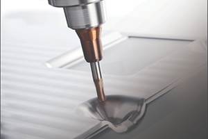
Relative to hard die machining, graphite milling is a much more robust process. The nature of graphite means that it is much more forgiving of "jerky" machine movements, tool runout and other process inadequacies than hard die machining. These deficiencies will still adversely affect graphite part quality, but likely will not cause the process to stop due to a broken tool. Furthermore, machining time for graphite electrodes is significantly less than that for equivalent hardened steel parts. Consider the electrode and hardened steel parts illustrated in Figures 1 and 2. The electrode in Figure 1 was machined in less than one hour with a maximum scallop height of 20-millionths of an inch and a total surface deviation requirement of <0.0004 inch.
The equivalent (male) form required almost four hours to machine in 52 HRc steel, while the female form required almost 10 hours in pre-hardened steel. The female form required a much longer time because of the long extensions for small diameter tools that had to reach the corner radii at the base of each cylindrical pocket (cylindrical boss on the male form). This severely limited cutting feedrates to prevent cutter breakage. The hard steel part did result in a finished piece that didn't need hand polishing. But once the electrode is machined, it can be employed in an EDM sinker with minimal supervision. This represents a significant benefit over machining of hardened steel.
Hard steel machining and the production of graphite each have their relative benefits and idiosyncrasies. Following the challenges associated with producing high accuracy graphite electrodes in a timely and cost-effective manner is the topic of discussion here.
Cutter Requirements
Graphite is a highly abrasive material, and tends to wear out cutters quickly. One of the greatest difficulties encountered when machining graphite is that cutter wear can reach unacceptable levels within the time required to machine a single, multi-featured electrode. As such, advanced tool coatings offer a significant benefit when producing graphite components.
TiAIN, or diamond-coated tooling, is highly recommended for production of tight tolerance graphite components because it helps to minimize wear and maintain part accuracy. Uncoated carbide tools can be used, but are best restricted to roughing and semi-finishing, when tool wear is less of a concern.
To help mitigate the effects of cutter wear, the use of tool measurement probes on the machine tool is highly recommended. Tool length measurement probes, preferably non-contract laser probes, are particularly helpful when it comes to validating the length and diameter of cutting tools and tracking their wear state. Non-contact probes are best because they allow the cutters to be measured while rotating. This enables runout to be taken into account as part of the measurement. Unlike metals, when graphite is machined, you don't get a continuous chip that has sheared off the workpiece. Instead, a combination of crushing and flaking occurs. Flaking is undesirable, particularly when finishing, because it appears as chipping of the surface. Using cutter geometry with a negative rate angle can reduce the amount of flaking and provide a larger crushing zone. This generates a better overall surface finish. Because a continuous chip is not created, a chip breaker isn't required on cutters used in graphite.
Process Design
Unlike hard die milling, the process design when machining graphite is less critical in the sense that a poorly designed process is less likely to lead to broken tools. But, a well-designed process is still imperative to produce high quality electrodes. While cutter breakage is less of a concern, the toolpath must be designed to avoid flaking and chipping of the surface. Entry and exit from the part should use a ramping approach, rather than a direct step into the surface. Sudden changes in chip load should also be avoided, again to prevent chipping of the workpiece. When developing a toolpath for electrode production, follow these guidelines to minimize overall machining time.
Carefully evaluate the relative merits of Z-level cutting and flow-line machining vs. parallel path cutting. While Z-level (or with flow-line machining) toolpaths often contain less air cutting, they can be very inefficient for parts with distinct, and disconnected, surfaces.
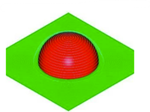
Break the toolpath up to optimize it for distinct part features. When producing a toolpath for a cell phone mold, for example, the machining of the buttonholes should be handled as a distinct operation from machining of the overarching surface of the phone. If the entire phone is machined with a monolithic toolpath, the machine must change direction much more often (as it dives in and out of the buttonholes while traversing the surface, for example). The result is lower average feedrates, due to acceleration and deceleration, and significantly longer cutting times. If the surface profile is machined, followed by a separate (Z-level) toolpath for the buttonholes, the paths can be optimized for each of these very distinct geometries (see Figure 3).
Match the toolpath to the machine to minimize the mass that must be moved to produce the part. Utilize as few machine axes as possible. Many toolpaths are created without regard for the machine in question. Aligning toolpath with the machine axis that carries the lightest load will extend the life of any machine.
Establish "correct" speeds and feeds to reflect changes in depth of cut, and the geometry of ball end mills. Ball end mills are not bottom cutting, so as the depth of cut changes, the effective surface speed increases as well. Keep this in mind when calculating the spindle speed and axis feedrates for a given cut and you will often find that higher speeds and feeds than initially expected can be used.
Very high spindle speeds and feedrates can be used when machining graphite due to the nature of the material. Inadequate consideration is usually given to the accelerations and servo gains required to support these high programmed feedrates, resulting in clipped surface geometry.
The use of contour optimization (i.e. look ahead systems) and gain switching features is of significant benefit in graphite machining because the feedrate can be managed by the CNC to eliminate gouging, and higher accelerations can be supported through gain switching. When using a contour optimization system, ensure that the CNC allows a specific part tolerance to be set, rather than simply operating in a nondescript "better" mode. Instead, a specific tolerance is required on all features, including 3-D contours. The CNC motion system must reflect this reality.
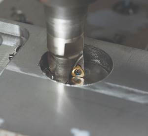
Graphite is unforgiving of surface finish defects, clearly reflecting even the smallest perturbations. As such, it is important to use a fine step over and small chordal deviation to optimize surface finish. This results in very large part programs, and given the high axis feedrates, often causes data starvation in the CNC. Careful consideration of the data processing capabilities of the CNC is necessary before releasing graphite-machining programs into production (see Figure 4).
A true high-speed CNC, designed for handling data intensive 3-D programs, is a must for high-speed graphite machining. On the other hand, this does not mean that NURBS is a necessity. High-speed point-to-point CNCs, and there are no extra costs associated with "NURBS options" for the CNC and CAM systems.
Coolant is rarely used when machining graphite because of the difficulty in separating the graphite from the coolant for proper disposal. Compressed air is typically used to remove dust from the tool-work interface, and to make the dust airborne so that it can be entrained in the flow of air typically used to remove it from the work area. Some shops use a chilled compressed air source to maintain a lower temperature at the tool.
Machine Tool and CNC Requirements Compared to hard die milling, a machine tool for graphite experiences lower cutting loads. A high degree of stiffness is still required because the feedrates and accelerations used on graphite will be higher, creating the need for excellent dynamic performance and resistance to dynamic loads. These accel/decel loads typically exceed cutting forces, even when working in hardened steel! Geometrically, the machine must be as accurate as a mill intended for hard die milling, and a high degree of damping is also required. Further, use the smallest machine possible when producing electrodes. The bigger the machine the more one gives up in dynamic performance, leading to longer cycle times and less accurate electrodes.
Spindles for graphite machining should provide very high speed, but clearly require less power than for hard die milling applications. Maximum spindle speed should be at least 20,000 rpm, and preferably 25,000 rpm or more. Because high spindle speeds and feedrates are used, the amount of thermal growth when machining graphite can be considerable, and the use of thermal control system is necessary to product graphite electrodes to a high degree of accuracy. Adequate sealing of the spindle nose to prevent contamination from graphite dust is a prerequisite for long spindle life. The taper should be outfitted with a taper air blast and an air seal to protect the front bearings of the spindle is preferred over a conventional labyrinth. The use of grease-lubricated spindle bearings is recommended over air-oil because it is unacceptable for oil to drip onto the part. Seek HSK tooling to minimize cutter runout.
While spindle speed calculations based on published sfm and chip-per-tooth values can indicate the need for speeds in excess of 50,000 rpm, consider the trade-offs between spindles that run at 30,000 or 40,000 and those at 50,000 or 60,000 rpm. At the higher speeds the ability to support larger diameter tools decreases significantly, as does the amount of power available for roughing and semi-finish operations. While we produce machines with speeds up to 60,000 rpm, we find the best overall compromise for a wide range of graphite applications to be an HSK40E or #25 taper 30,000 rpm spindle providing 6kW of continuous power. Such a spindle can support tools over 0.5"o, as well as 0.010" and smaller cutters. For more specialized electrode production, naturally slower or faster spindles may be appropriate.
The CNC's data processing speed is more important for graphite machining than hard die milling applications because feedrates are typically higher. Therefore, the program must flow through the CNC at a faster rate when machining graphite. The ability of the CNC/machine system to provide a high degree of dynamic accuracy (as measured in part by the ball bar test) remains critical when producing electrodes.
Consider also whether the CNC has advanced features to support the production of contoured electrodes. Features such as 3-D cutter compensation allow the CNC to automatically compensate for errors in ball mill cutters without having to re-post the surface geometry. 3-D cutter compensation also can be used to create undersized electrodes without having to create new toolpaths in CAM. Such features can save significant time in the CAM department.
Look for machines that can provide ball bar results of better than 0.0004 inch TIR on a 12-inch circle at 20 ipm or more. Performance less than this will not support the production of electrodes to better than 0.0005-inch once other errors sources (i.e. thermal, runout, contouring error, set-up errors) are taken into account.
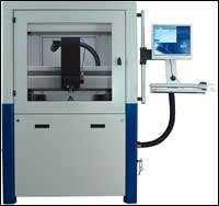
When cutting dry dust removal from the machine work area is of paramount importance. A machine intended for graphite production should provide integrated dust removal, and a well-designed system for protecting the machine subsystems (such as the drive trains) and shop environment from contamination. While machines without graphite protection can clearly produce graphite parts, their ball screws, linear ways, and spindles will experience accelerated wear and loss of accuracy (see Figure 5).
The Role of Automation
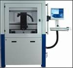
To fully optimize the production of electrodes, it is often necessary to implement an automated production environment. An automated electrode production system must provide adequate tool and part storage to allow 72 hours or more of unattended operation. As important as the automation equipment itself is the capability of the machining center. It must be accurate and repeatable enough to eliminate the prospect of thermal drift over time. Likewise, the ability to measure and compensate for tool wear also is important. Figure 6 illustrates a typical automated electrode production center.
A Final Note
When producing electrodes, many smaller shops find that they do not have enough work to dedicate a machine to this purpose. When considering a machine tool for the production of electrodes, it is important to consider what other tasks can be assigned to the machine. In smaller operations, a high-performance machine tool may produce electrodes so quickly that it sits idle for several hours each day.
If the machine also is capable of supporting hard die milling or other metal cutting operations a much higher return on investment can be achieved. Look for machines which can be easily switched between dry graphite machine and steel cutting. For example, the parts in Figure 1, 2 and 4 were all cut on the same machine.
Related Content
Treatment and Disposal of Used Metalworking Fluids
With greater emphasis on fluid longevity and fluid recycling, it is important to remember that water-based metalworking fluids are “consumable” and have a finite life.
Read More6 Ways to Optimize High-Feed Milling
High-feed milling can significantly outweigh potential reliability challenges. Consider these six strategies in order to make high-feed milling successful for your business.
Read MoreMoldmakers Deserve a Total Production Solution
Stability, spindle speed and software are essential consideration for your moldmaking machine tool.
Read MoreRead Next
How to Achieve Efficiency in Graphite Electrode Milling
A look at the technological advancements of HSM centers that provide the efficiency and quality required for milling graphite electrodes, particularly small electrodes with intricate features and thin-walled characteristics.
Read MoreReasons to Use Fiber Lasers for Mold Cleaning
Fiber lasers offer a simplicity, speed, control and portability, minimizing mold cleaning risks.
Read MoreHow to Use Continuing Education to Remain Competitive in Moldmaking
Continued training helps moldmakers make tooling decisions and properly use the latest cutting tool to efficiently machine high-quality molds.
Read More
