How to Achieve Efficiency in Graphite Electrode Milling
A look at the technological advancements of HSM centers that provide the efficiency and quality required for milling graphite electrodes, particularly small electrodes with intricate features and thin-walled characteristics.
The demand continues to grow for high speed machining centers used in the milling of graphite electrodes for die-sinking EDM. For awhile, it seemed like the advancements in the machining of hardened steel might make graphite electrodes obsolete; however, there are factors that continue to make electrodes, and thus high-speed machining, a critical process for moldmaking.
Specifically, machining times associated with rigid, hardened steel are still significantly longer than for those required for milling graphite electrodes. Both runout and tool deflection frequently result in tool breakage when milling pockets, cavities or intricate 3-D topography in hardened steel. When tools break it not only interrupts the machining of the steel, it also can impact quality and lead to part rejection and material waste.
So, for the foreseeable future, graphite electrodes will reign supreme—and moldmakers who employ the most efficient equipment for machining them stand to widen the competitive gap between themselves and those slugging it out with hardened steel.
Micro Tooling Basics: Challenges and Solutions
With graphite, the magic words are high speed. High speed machining centers with 30,000- to 60,000-rpm spindles are capable of accelerated feeds that serve to reduce cycle times and improve surface finish, as well as edge quality. The motors required to run these spindles are smaller and lighter and this results in lower cutting forces and reduced tool breakage. This is particularly critical because many electrodes are intricate and the production of them involves small, fragile micro tooling.
Spindle
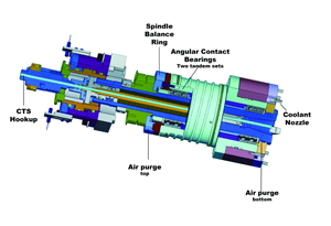
The smaller the tools, the higher the spindle speed needed to efficiently machine quality parts and avoid tool breakage. High frequency spindles with speed ranges up to 60,000 rpm are ideal for milling, drilling and engraving graphite electrodes using micro tools. High speed machining technology uses high rpm rates, taking a smaller stepover, but with significantly increased feedrates.
Move your hand through the flame of a burning candle. If you move too slowly, there’s enough time for the flame to cause damage. But if you sweep your hand swiftly through the flame, there’s insufficient time for the fire to damage your skin. The same principle applies to high speed machining with micro tooling. Move fast, and there’s insufficient time for heat to feed back into the part and cause issues.
Using small micro tools for graphite or virtually any other material simply isn’t as easy as finding an adapter to hold a tiny tool in a 40-taper spindle on a conventional CNC machine. Because that spindle was designed for large tools like a three-inch fly cutter intended to hog out deep cuts in dense substrates. As such, it has so much torque and force that it just breaks small tools, which is both inefficient and very costly over the long haul.
The only option an operator has in this situation is to slow the rpm and feedrates down to a crawl, and this isn’t efficient either because it results in unacceptable cycle times. A vivid, and perhaps comical, analogy is the Hemi-powered pick up truck versus the sportscar. The reality is that you wouldn’t compare the two or even consider racing them against on another. Why? Because the truck was designed with the power and force to haul or tow enormous mass, while the sports car was designed for speed and maneuverability. In essence, conventional CNC manufacturers who tout the ability to run micro tools are like an auto manufacturer putting a spoiler and racing stripes on a clunky SUV and claiming that it now possesses the same qualities as a Porsche. Well, just like you can’t put a spoiler and racing stripes on an SUV and expect it to perform like a sports car, you can’t retrofit a high speed spindle onto a clunky conventional machine and expect it to efficiently accomplish high speed machining with micro tooling.
Geometry
Just like conventional CNCs can’t be retrofitted to efficiently run microtools, conventional tooling geometry (for larger tools) can’t just be scaled down for micro tooling. The geometry of the tooling used to mill electrodes plays a key role in both quality and efficiency. Scaling down the tool geometry of larger diameter tools to a smaller format yields unacceptable feedrates and unsatisfactory finishes.
Tooling requirements change when tool diameter is decreased and spindle speed is increased. Conventional tooling using inserts is not appropriate for micro tooling applications. This is primarily due to the high rpm rates rather than the tool diameter.
Tool Wear
Increased rpm rates require properly balanced tools with significantly increased chip room to assure proper chip removal. While geometry can assist in both quality and efficiency when milling graphite, tool wear is still a concern due to the inherently abrasive nature of this material. Specialty tool coatings can be a weapon in battling excessive wear. Some coatings to consider are diamond coating, titanium aluminum nitride coating (TiAIN), which is often used for applications in steel and, finally, aluminum chromium nitride coating (AlCrN)—generally used for applications in very hard aluminum (such as cast aluminum or sand cast aluminum), but which has shown effectiveness with other abrasive substrates like fiberglass.
System Feature Considerations
Dust Protection
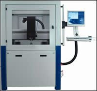
Since graphite is such an abrasive material, protection of the CNC’s working parts from graphite dust is extremely important. Some machine tool manufacturers have developed turnkey solutions1 that address these application-specific needs.
Look for graphite machines that feature:
- Covered linear guidances and ball screws with positive air flow to block abrasive materials from getting into the motion mechanics of the high-speed machining center.
- Sealed housings for all motion-control electronics and motors to protect against contamination of the machine control system.
- A full enclosure complete with safety lock that is equipped with a connection to an air flow system for dust extraction. This machining system is ideal for machining materials such as graphite, glass-fiber composites, ceramics or any abrasive material.
Tool Length Measurement
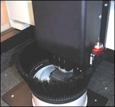
Another feature to look for on an advanced machine—which is beneficial in the milling of graphite—is tool length measurement that can compensate for tool wear. This tool sensor/replacer system is made up of three separate components working in conjunction:
- Toolchanger
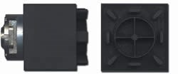
The toolchanger is a rack or tray that has space for spare tools as well as empty sockets for placing broken tools. Machine operators can stock the rack with spare tools, thereby having a ready supply should tools break during lights-out or unattended operation. - Tool checker
The tool checker is a mechanical sensor that measures tool length. This is the instrument that actually detects the worn or broken tool in the first place. - Software
The software is a macro program that can be set up to run a tool check after executing a number of lines of code. For instance, a tool check macro can initiate a check after every 500 lines of code. This is known as an if/then statement, in other words, “Measure this tool; if the length is shorter than the listed parameter, then change the tool.”
Summary
So, as machining centers inch toward the ultimate goal of efficiently milling hardened steel in a single step, the technological advancements of high speed machining centers are staying ahead of the curve in providing the efficiency and quality required for the milling of graphite electrodes. This process is instrumental in moldmaking and will likely be the mainstay of the industry for some time to come.
References
1 Datron Dynamics, Inc. (Milford, NH).
Related Content
Revisiting Some Hot Runner Fundamentals
What exactly does a hot runner do? If you’ve been in the injection molding industry for any length of time, you might think the answer is obvious, but it is not.
Read MoreThe Benefits of Hand Scraping
Accuracy and flatness are two benefits of hand scraping that help improve machine loop stiffness, workpiece surface finish and component geometry.
Read MoreMachining Center Spindles: What You Need to Know
Why and how to research spindle technology before purchasing a machining center.
Read MoreWhat You Should Consider When Purchasing Modified P20 Steel
When buying P20 steels that have been modified, moldmakers must be aware of the variations and key issues that affect delivery, cost and lead times.
Read MoreRead Next
Reasons to Use Fiber Lasers for Mold Cleaning
Fiber lasers offer a simplicity, speed, control and portability, minimizing mold cleaning risks.
Read MoreHow to Use Continuing Education to Remain Competitive in Moldmaking
Continued training helps moldmakers make tooling decisions and properly use the latest cutting tool to efficiently machine high-quality molds.
Read More


