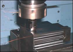
How to Select the Right Carbide Insert
The menu of available coatings for carbide inserts has expanded ten-fold in the past 10 years. Selecting the one that can produce low cutting forces with smooth cutting action, good surface finish and long tool life becomes the user's dilemma.
The selection of the most advantageous tooling material for molds and dies has become as sophisticated a factor as the design of the tooling itself. The use of new materials, new harder coatings for materials, pre-hardened materials and combinations of materials in molds and dies continues to complicate the manufacturing engineer's ability to select the optimum cutting tool as it relates to material machineability, hardness and desired surface finish.
Couple this with newer high-speed machines and new oil mist and dry machining techniques as well as better surface finish requirements, and you have created a real cutting tool insert selection "dilemma" for the moldmaker (see Figure 1).

Figure 1: Assortment of some of today's different carbide and ceramic cutting tool inserts.
Most moldmakers do not have the luxury of a machining lab or even the time to do machining evaluations for different cutting parameters. Short leadtimes and precision machining defines the work.
New insert style cutter designs, particularly for milling, have improved the ability to quickly and efficiently rough-in mold cavities, and perform mold squaring and contouring as well as profiling and finishing. The development of multifunction milling tools that can use a wide variety of different insert style geometries now allows all types of milling to be performed with one cutter - providing more flexibility and lower cost. Some new modular milling system designs even allow the user to simply change milling heads on variable length adapter shanks to provide versatility. And with the addition of new "shrink-fit" toolholder technology that takes advantage of the performance benefits of induction heating, the toolholder and shrink-fitting a cutting tool into it, concentricity and rigidity for deep cavity tools have been greatly improved. These advancements have given the moldmaker better metal cutting options than have been previously available. But when it's all said and done, it's the carbide cutting tool insert that really makes it work. And the options here can be overwhelming. For example, it's not uncommon for a carbide insert manufacturer to have more than 20 different carbide substrate grades that can be coated with titanium nitride (TiN), titanium carbonitride (TiCN), titanium carbide (TiC), aluminum oxide (Al2O3), zirconium carbonitride (ZrCN), titanium aluminum nitride (TiAlN) or aluminum titanium nitride (AlTiN). These coatings can be applied individually or in combination by a physical deposition process (PVD) or a chemical deposition process (CVD) or even in a multi-layer CVD process that permits up to 70 ultra-thin layers to be deposited.
Coatings do significantly improve wear resistance, increase tool life and enable higher speeds and feeds to be achieved. PVD and CVD coatings are differentiated by the deposition processing temperature. The PVD process is a lower temperature process providing a finer crack-resistant coating grain structure with a low coefficient of friction. As a result, PVD-coated inserts can have sharper cutting edges.
Now add several of the cermet ceramic grades to the list and it is easy to see how proper selection can become a real nightmare. So it is important to first consider where and why insert failure occurs as well as some of the application basics for machining different mold materials. The recommendations for specific insert types will serve as a good starting point.
Tool Failure Analysis
The predominant failure conditions of cutting tool inserts used in moldmaking is thermal cracking, followed by erosion around the cracks, build-up of workpiece material (analogous to material welding on the edges of tool inserts) and eventual edge chipping. Workpiece materials like H11, H13, D2 and A2 tool steels promote thermal cracking and edge chipping of tools.
Thermal cracking is accentuated by the use of coolants and high feedrates during machining. Conventional CVD-coated carbide tools often are limited in combating thermal crack resistance. Conventional CVD coatings like TiC, TiCN and TiN provide limited thermal barrier properties but have high stability, oxidation resistance and chemical resistance. Al2O3 or AlO3/ZrO2 composite oxide coatings provide enhanced chemical wear resistance as well as thermal barrier protection. The compromise with these types of coatings is their limited fracture toughness properties. Tensile stresses are typically higher in high temperature (~1000'C) CVD coatings.
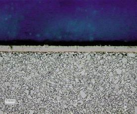
Figure 3: Photomicrograph of multi-layer MLCVD TiN/TiCN-coated carbide. This is a very tough substrate, coated with 62 alternating ultra-thin layers of titanium nitride and titanium carbonitride. This coating resists microcrack propogation for longer, more dependable tool life.
Moderate temperature (~850'C) multi-layer MTCVD coatings like TiCN or ZrCN have lower magnitude of tensile stresses and are better suited to combine the properties of fracture toughness, abrasive wear resistance, chemical wear resistance and thermal crack resistance when used in combination with oxide coatings (see Figure 3).
In the last five years, there has been a tremendous advantage in using PVD coatings based on TiAlN compositions. The high oxidation resistance, high chemical stability, high hot hardness and enhanced thermal barrier properties of these types of PVD coatings facilitates their use in high-speed (1,000 to 1,500 sfm) dry machining applications. Without question, machining productivity is enhanced with the use of PVD TiAlN coatings (see Figure 4).
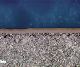
Figure 4: Photomicrograph of TiAIN PVD-coated carbide with excellent wear and crater resistance.
Mold Materials
Because milling makes up the majority of the machining performed on molds and dies, it is best to focus on some of today's common mold materials. Also, most carbide insert manufacturers have similar product in terms of carbide grades and coatings, so the descriptions will be generic in nature. However, top form geometries will typically be different from one manufacturer to the other, and certain geometries do perform better than others.
Aluminum
Aluminum is the preferred mold material for some segments of the plastic molding industry. Metal removal rates can be as much as eight to 10 times faster than machining steel. In recent years, aluminum producers have developed better high-strength materials that have hardness characteristics that range from 158 to 168 Brinell. It is difficult to machine very smooth surfaces on aluminum, so polishing becomes an important operation in the final process.
Generally speaking, milling aluminum requires a C2 carbide grade for roughing and a C3 for finishing. These are general purpose milling grades with a medium grain that have excellent wear resistance for roughing and finishing applications where sharp edges are required. From 700 to 2,000 sfm can be achieved at a feed-per-tooth of .004 to .014. Also, TiC/TiCN cermet grades are ideal for wrought aluminum materials where good edge strength and lubricity are required. From 1,500 to 2,500 sfm can be achieved with these types of ceramic inserts. For endmills and face mills, feed-per-tooth usually ranges from .006 to .014 inches per tooth. Insert designs should have a good positive rake angle to insure that chips leave the cutting edge as quickly as possible (see Figure 5).
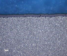
Figure 5: Photomicrograph of cermet substrate. This is a medium-duty cermet milling grade with good edge strength and lubricity that is suitable for light roughing to finishing operations of steels, stainless steels and ductile irons. It is excellent for soft, gummy materials, and wrought and cast aluminums.
In most cases, uncoated carbide grades are all that is required. Aluminum is easy to cut and the added expense for any type of coating to improve wear life usually is hard to justify.
However, when very high-speed machining is being performed, PCD inserts brazed with poly-crystalline diamond are the insert of choice because of the superior finish that can be produced at elevated speeds.
Beryllium Copper
Copper-based alloy materials for molds bring a number of positive benefits to the moldmaker in terms of thermal conductivity characteristics. They also have hardness levels that can range from 10 to 40 Rc, nearly double that of aluminum. However, the C2 carbide grades that apply to machining aluminum also apply here. Recommended feeds and speeds would be somewhat less for both roughing and finishing. Around 330 to 660 sfm is realistic, at a feed-per-tooth of .003 to .008 inches per tooth. Again, insert designs with at least a seven degree positive rake angle are recommended.
P20 Tool and Die Steel
This is a commonly used mold steel that is typically alloyed with chromium, nickel and molybdenum. It is usually hardened and tempered with a uniform hardness of approximately 32 Rc. Very smooth surface finishes can be achieved with P20 steel. However, the menu of possible insert grades and coatings expands, depending on the machining variables and the surface finish desired. Some type of coated insert or cermet will probably be the best solution because higher feedrates can be achieved. C5 and C6 carbide grades are suggested for roughing, and C6 and C7 for finishing. A good impact-resistant carbide substrate is required - one that combines well with a CVD coating of TiN for lubricity and wear resistance or a multi-layer CVD coating of TiN/TiCN/Al2O3/TiN. Because of their good edge strength, TiC/TiCN cermets also can be used. Machining speeds from 300 to 600 sfm can be achieved for roughing and 250 to 625 sfm for finishing.
With the various coatings, feedrates can be from .005 to .008 inches per tooth. Uncoated carbide grades also can be successfully used - those with good edge and impact strength. However, the slower machining speeds that are required are really impractical today.
It should be noted that harder tool steels - those over 45 Rc - also are being used today, all in an attempt to produce better surface finish and eliminate any polishing operations. A good starting point would be to try those cutting tool inserts that work on P20 steel and experiment with the feeds and speeds.
Ferritic and Martensitic Stainless Steels
These steels include the full range of 400 series stainless steels. Typically, these stainless steels have hardness ranges from 50 to 56 Rc. A good heavy-duty carbide substrate is required here. Inserts with CVD coatings of TiC/TiCN/TiN or TiN/TiCN/Al2O3/TiN perform well. Also, PVD coatings of TiN are effective as well as Ti/TiCN-coated cermets. As usual, it all comes down to speed. With the CVD coatings you can run faster, and of course the cermets are the fastest - featuring roughing from 360 to 650 sfm and finishing from 400 to 850 sfm. Feed-per-tooth is fairly consistent at .004 to .012 inches per tooth.
High Temperature Alloys
Moldmakers continue to experiment with harder nickel- and cobalt-based mold materials to increase mold life. One drawback has been the ease of machineability of these materials. They are very hard, sometimes over 57 Rc. Typically, uncoated carbide grades have been the only available option. Today, however, new AlTiN coatings with a high aluminum content are very effective because of their higher hardness and oxidational stability. The coating is applied with a unique sputter ion process that deposits a dense and even coating. The coating acts as an insulator, transferring the generated heat to the chip, not the insert. Roughing speeds range from 80 to 115 sfm, with a finishing speed of 90 sfm. Feeds range from .004 to .012 inches per tooth. Diamond coatings are still in the development stages, but ultimately will be an option that will make machining these high-temperature hard-alloy materials more feasible (see Figure 7).
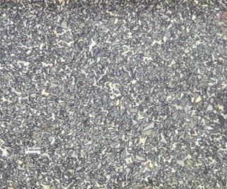
Figure 7: Photomicrograph of AITiN PVD-coated carbide that features excellent wear resistance and toughness. It is ideal for machining titanium and titanium alloys, and performs roughing and finishing at higher speeds where part size and surface finish are critical.
Conclusion
As moldmakers continue to utilize different mold materials to optimize the efficiency of the molding process, machineability of those materials and the economics of the metal cutting process will continue to be a dynamic one. Cutting tool insert manufacturers will continue to develop new grades, coatings and top form geometries to improve wear and tool life of those cutting tools, which is already being found in new micrograin carbide grades (<0.4fm) with PVD TiAlN coatings specifically developed for machining steels pre-hardened over 54 Rc. In addition, there is a trend toward dry cutting processing to increase economic efficiency and meet the expanding ecological requirements. Coatings will play a crucial role here with respect to improving thermal energy management, lubrication, low coefficients of friction and the kind of chip evacuation required for dry cutting applications. For example, a ZrO2 coating is very effective in dry machining due to its high fracture toughness and low friction coefficient.
In most cases, there never will be one cutting tool insert solution that works for everyone. There are too many variables with respect to different machines, various coolants, speeds and feeds, and machining environments. What this article has attempted to show, in as brief a context as possible here, are basic starting points for insert selection for the various mold materials. The ultimate selection is left to you, hopefully now possessing a better knowledge.
Related Content
6 Ways to Optimize High-Feed Milling
High-feed milling can significantly outweigh potential reliability challenges. Consider these six strategies in order to make high-feed milling successful for your business.
Read MoreTolerancing in Mold Design, Overcoming Cutting Tool Vibration, SPE MTD Updates & More Most-Viewed May Content
Every month, MMT draws inspiration from its diverse readership's wide-ranging interests, from mold design tolerancing to cutting tools and beyond. Here are May’s top 10 most-viewed articles, based on Google Analytics.
Read MoreTen Things You Need to Know about Circle Segment Milling
Considerations for evaluating if circle segment end mills or conical barrel cutters are right for your mold machining applications.
Read MoreRead Next
What Ceramic Insert Technology Can Do for Moldmakers
The benefits of hard milling with ceramics in mold manufacturing.
Read MoreReasons to Use Fiber Lasers for Mold Cleaning
Fiber lasers offer a simplicity, speed, control and portability, minimizing mold cleaning risks.
Read MoreHow to Use Continuing Education to Remain Competitive in Moldmaking
Continued training helps moldmakers make tooling decisions and properly use the latest cutting tool to efficiently machine high-quality molds.
Read More


.png;maxWidth=300;quality=90)


