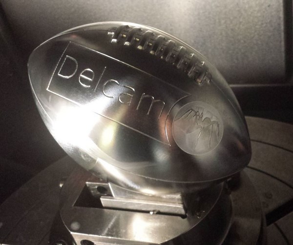
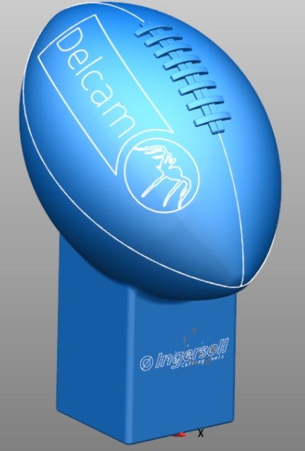
VIDEO: How to Machine a Football
We are in the heat of football season, so what better time to showcase how a football is machined.This video shows a model American Football being created out of 6061 Aluminium with a Toyoda UX-570 5 axis machine with a 3D offset toolpath: 0.032 dia cutter mounted in a Typhoon HSM Jet Spindle using thru spindle coolant at 36,000 RPM and 400 IPM.

While presenting the latest developments of its CAM system for high-speed and five-axis machining and its feature-based programming software, Delcam machined a metal replica football, one programmed with PowerMILL and one with FeatureCAM. Check it out here.
This demo happened during a meeting held at Ingersoll Cutting Tools in Rockford, Illinois, and included live cutting demonstrations on Ingersoll’s Mori Seiki MV-65 and Toyoda UX570 CAT 40 machines. Recognizing the divided loyalties of the region’s Delcam customers, one was produced with a Chicago Bears theme while the other featured the Green Bay Packers.
The new release of PowerMILL includes improvements to the Vortex high-efficiency area-clearance strategy, expanded collision checking to also cover near misses, and more efficient raster finishing. Vortex produces safe toolpaths with a much deeper cut by using a controlled engagement angle that maintains the optimum cutting conditions for the whole toolpath.
Companies using four- or five-axis machines with trunnions or similar tilting tables will benefit from new options that distribute PowerMILL’s toolpath points, so that the machine’s gimbal-lock position is avoided and a smoother motion results.

As well as including the latest developments in the Vortex strategy, the 2015 version of FeatureCAM incorporates a range of enhancements in three-axis milling, two-axis and five-axis drilling, turning and turn-mill, and wire EDM to make the software even more powerful and easier to use.
Related Content
-
Ceramic End Mills Excel in High-Speed Roughing, Milling of Heat-Resistant Superalloys
Long-lasting, five-flute Cera-Cut end mills introduced by Emuge-Franken USA are designed to consistently tackle high temperature resistant metals and hardened tool steels.
-
Neck Relief Option Optimizes End Mill Cutting Strength
M.A. Ford’s TuffCut family addition, the nine-flute XT9 380N series, meets high-speed machining of demanding deep pocket milling applications head-on, for tool steels and other materials.
-
Double-Column Machining Centers Improve Accuracy, Speed of Mold Machining
IMTS 2024: Takumi highlights its UA400 five-axis and VC1200 three-axis machining centers for mold machining, designed to minimize thermal growth and accelerate feed rates.


