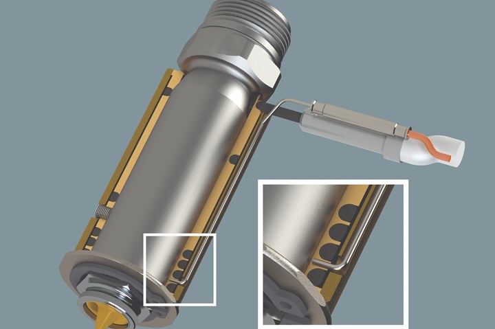
The tip of a thermocouple must be properly seated. Images courtesy of INCOE Corporation.
The root cause of a recent part defect was reportedly the delivery of a melt that was too hot. The true root cause, however, was something else entirely.
After considering whether the unseated thermocouples were falsely reading air instead of steel and autotuning the existing temperature controller, the company examined the cables. Often, the thermocouple wire will be a K-type instead of the required J-type, but again that was not the case here. However, what was discovered was that the molder was using copper wire.
Here is an example to demonstrate why shops should not use copper wire cable to monitor thermocouple feedback to the temperature controller:
- Air temperature at (within) the mold electrical junction box (Temperature B): 100°F
- Air temperature at the controller (Temperature A): 75°F
- Setpoint: 480°F
- Using correctly-wired thermocouple (J-type or K-type) extension wire.
If the hot end is 480°F, the Analog Input (AI) terminal block is 750ºF and the electromotive force (EMF) is “seen” at the AI for any t/c type, then PV = 480°F - 75°F + 77°F = 482°F. When using t/c wired cable as required, the temperature at the mold electrical junction box adds a “zero” unknown error.

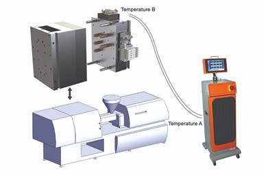
A diagram describing why you should not use cables with copper wire: air temperature at (within) mold electrical junction box (temperature B) = 100°F; air temperature at controller (temperature A) = 75°F; setpoint is 480°F.
With copper extension wire, the PV equation remains the same plus an “error” unknown to the operator (or the temperature controller). Since the PV equation does not change, neither does the temperature controller's indicated actual temperature. What does exist, but is not indicated, is the "error" that is the actual temperature at the tip of the t/c, which is the added "error" heat to the plastic.
If the hot end is 480°F, the AI terminal block is 75°F, and the EMF “seen” at the AI is (still) then PV = 480°F - 75°F + 77°F = 482°F. However, when using copper wire, another junction is added that is not part of the temperature controller logic. The error is not visually indicated on the controller.
The t/c-copper junction is at 100°F (Temperature B): Temperature B (100°F) -Temperature A (75°F) = 25°F. The real actual temperature at the tip of the thermocouple is the real temperature of the melt at 505°F.
Again, the real actual temperature is 505°F because you cannot program the temperature controller with the cold junction and another junction (always a variable). The user has no way of knowing this and trusts the indicated/actual temperature readout on the controller as gospel.
Also, the inside temperature of a mold junction electrical box mounted on the top side of a mold can experience temperatures well over 100°F. These temperatures will add and subtract from the unknown error relative to the time of the day and season, which may then impact the temperature within the shop at daytime or nighttime.
The bottom line is that you should not use cables with copper wire to monitor thermocouple feedback to the temperature controller for any molding application, especially those with “technical” parts and material.
Related Content
Hands-on Workshop Teaches Mold Maintenance Process
Intensive workshop teaches the process of mold maintenance to help put an end to the firefighting culture of many toolrooms.
Read MoreHow to Transition From a Cold to Hot Runner Mold
Reducing cycle time and costs while also freeing up your machines for other projects are advantages gained by using hot runners that no one can ignore. But where does one begin transitioning from cold to hot runners?
Read MoreThe Ins and Outs of Hot Runner Temperature Control
A training checklist that explains the why and how of proper hot runner temperature control and system management.
Read More5 Hot Runner Tips for Moldmakers and Molders
Best practices for initial hot runner tryouts and effective preventive maintenance.
Read MoreRead Next
Reasons to Use Fiber Lasers for Mold Cleaning
Fiber lasers offer a simplicity, speed, control and portability, minimizing mold cleaning risks.
Read MoreAre You a Moldmaker Considering 3D Printing? Consider the 3D Printing Workshop at NPE2024
Presentations will cover 3D printing for mold tooling, material innovation, product development, bridge production and full-scale, high-volume additive manufacturing.
Read MoreHow to Use Strategic Planning Tools, Data to Manage the Human Side of Business
Q&A with Marion Wells, MMT EAB member and founder of Human Asset Management.
Read More


