Tradition Accelerated
CAD/CAM software gives manufacturers the time to create new products and stay on the cutting edge.
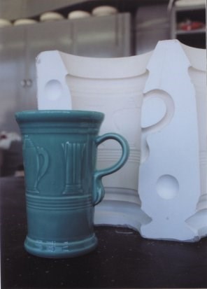
Founded in 1871 in East Liverpool, OH, and later moved across the Ohio River to Newell, WV, the Homer Laughlin China Company was one of the first whiteware plants in the United States. Today the company's operations span 37 acres and more than a mile under roof. Homer Laughlin is one of the nation's largest potteries and a leading provider of commercial foodservice ware, as well as the creator and sole distributor of the classic, colorful Fiesta(r) line, one of the most collected china products in the world (see Figure 1).
Homer Laughlin maintains its long tradition of leadership and success through a balance of traditional and state-of-the-art manufacturing techniques. Now, to speed new designs to market, it is embarking on the application of advanced CAD technology in its operations.
The Complex Way to China
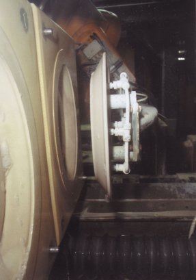
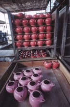
Homer Laughlin produces its chinaware in basically four ways: jiggering, ram pressing, casting and pressure casting. In jiggering, clay is placed on a mold of the face of the ware and a spinning jigger tool pushes it out to the ends of the mold while creating the back contours of the piece (see Figure 2). The ram press process uses molds representing the front and back of a piece that are pressed together around the clay. In casting, liquid slip is poured into a plaster mold to form the piece. In pressure casting, liquid clay "slip" is pumped into a two-sided porous resin mold under pressure. As the mold fills, the pressure rises, forcing out water and air. Computer-controlled and robot-fed pressure casting systems can produce a solid piece of ware from liquid slip in a short amount of time (see Figure 3).
In each of the processes, firing results in an 11 percent shrinkage in size from molded piece to final ware (see Figure 4). "People think china just pops out. It's actually a very complex process," says Joe Geisse, Homer Laughlin master artisan.
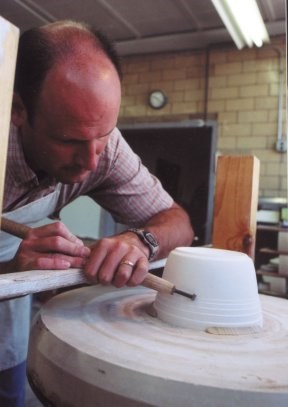
Every production method begins with a model. Model making is the first step of a process that continues through the creation of intermediate block molds and case (reverse) molds, which are then used to make the production molds. Models also are a key part of the creative design and approval process. Traditionally, Homer Laughlin has hand-carved the plaster models of its ware. "It doesn't get any more old school than here," Geisse says. "When we make a piece of ware, we go through a time-consuming process of making profiles and mixing up plaster. After it gets hard, we use turning tools to achieve the shape we want." (See Figure 5) Changing a plaster model can take time. "If the customer wants a change, you may have to cut a little bit of plaster away. If you have the plaster on the model, that's fine. If you don't have the plaster, you have to start all over again," Geisse notes.
Move to CAD
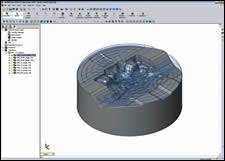
The fast-moving marketplace, the advent of advanced manufacturing technologies such as pressure casting, and overseas competition prompted Homer Laughlin management to look at ways to speed up its prototyping and manufacturing processes. The goal was to make models faster and eliminate repetitive, time-consuming steps in manufacturing. After researching available CAD programs and enlisting the help of CAD/CAM solution provider Design & Software International, Inc. (Fairfield, OH), Homer Laughlin chose the PowerSHAPE package from Delcam International. Modeler John Stoakes' research convinced them that PowerSHAPE is more user-friendly than other programs, and "the application is geared more toward what we need to do," Stoakes says. "We tend to find that people in this industry want to see a virtual 3-D model." PowerSHAPE enables Homer Laughlin to create this type of model much quicker than the traditional methods.
Design & Software president Jim Caliguri said PowerSHAPE has unique features that are especially useful for the work at Homer Laughlin. "For instance, the Mold Wizard automates some of the things they do for creating the molds," he comments. "They draw a model on the computer, then they use PowerSHAPE to create two mold halves. PowerSHAPE has built-in features to help generate complex parting lines and split the molds in half, as well as other things that have to be done for every mold."
Benefits of PowerSHAPE
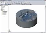
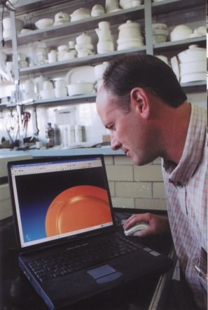
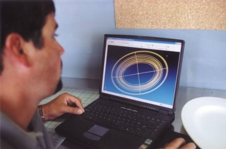
Geisse and Stoakes note that PowerSHAPE benefits Homer Laughlin in many ways. First, it accelerates new product design and approval. "If a customer is unsure about his needs," Stoakes says, "we can look at basic shapes and make changes on the computer screen, as opposed to carving a model then having the customer say, 'No, that's not what I want.'" (See Figure 6.) Geisse adds, "We can draw a piece on the machine then start printing it out and comparing until we get the actual piece that we want."
And although many customers do want to hold a model, others want to work with computer-generated drawings. "I can send them drawings in several different views, with measurements in volume," Stoakes says.
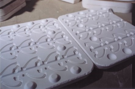
The CAD program can eliminate the need to carve plaster models. "We complete a model in the computer, then we build a press mold around it and send that file out to have a press mold milled from it. When we bring that press mold back we pour in liquid plaster. When we open it, we have a 3-D plaster model that we're able to use for several of our different applications," Geisse says. Updates to the model require only alterations to the electronic file, not carving a new model altogether.
Speeding Production
PowerSHAPE also will permit Homer Laughlin to significantly reduce the time it takes to get a piece of ware into production. Geisse notes that the multiple steps currently involved in creating molds for cup handles points out how PowerSHAPE will help the company save weeks of work.
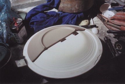
After a customer picks a design for a cup handle, a solid model is made. Then a "blocker and caser" technician begins a tedious process that can take up to a month and a half. First, he makes a two-sided press mold from the model and molds 24 copies of the handle. Then by pouring plaster in only half of the press mold, he makes 24 handle halves. The halves, connected by a gutter called a tree, are glued down on a flat sheet of plaster. Pouring plaster over the half-handles and tree produces half of a block mold. Next, the half handles are taken out of that mold and the solid handles put in, so the other half of the mold can be poured. Finally, from the two sides of the multi-handle block mold, case molds are made, which are used to make the final molds used in production (see Figure 7).
The use of PowerSHAPE will eliminate the repetitive copying of handles and halves. The array of handles and "tree" can be set up on the computer screen, and the electronic data fed to a CNC milling machine to make a multiple cavity, two- sided mold. From that mold, case and production molds can be made. Instead of taking 45 days, the process will be completed in 20 days or less.
Free to Create
To date, Homer Laughlin uses PowerSHAPE to create electronic files for models and molds, which they send to an outside contractor for milling into press molds.
Geisse says, "John and I like the plaster work. I'm not a big computer fan, but I do see the huge advantages of using them. I've been doing this since 1990, and I've made enough molds that I don't want to make any more! I'd rather spend my time and my skills creating new products and trying to stay on the cutting edge. PowerSHAPE is going to give us the time and capabilities to do that." (See Figure 8.)
Related Content
Domestic Collaboration Yields Efficiency and Budget Gains For Innovative Tooling Project
Pyramid Molding Group and Lettuce Grow partner to develop optimal tooling for a compact Hydroponic Farmstand.
Read MoreHammonton Mold, ADOP France Forge Strategic Partnership in Injection Blow Moldmaking
Hammonton Mold Inc., a leading full-service mold shop based in New Jersey specializing in injection blow molds (IBM), proudly announces its official partnership with ADOP France, a prominent IBM mold manufacturer based in Normandy, France.
Read MoreNavigating Economic Resilience and Consumer Trends
Consumer behavior provides mold builders insight into the evolving market dynamics of goods and services that helps strategic planning.
Read MoreMMT Chats: Digitalizing Mold Lifecycle and Process Performance
MMT catches up with Editorial Advisory Board member Bob VanCoillie senior manager of Kenvue’s mold management center of excellence outside of Philadelphia to discuss mold management via tooling digitalization and OEM expectations and opportunities.
Read MoreRead Next
Seamless Integration Between CAD and CAM Applications
How to avoid “walls” between mold design and manufacture.
Read MoreAre You a Moldmaker Considering 3D Printing? Consider the 3D Printing Workshop at NPE2024
Presentations will cover 3D printing for mold tooling, material innovation, product development, bridge production and full-scale, high-volume additive manufacturing.
Read MoreReasons to Use Fiber Lasers for Mold Cleaning
Fiber lasers offer a simplicity, speed, control and portability, minimizing mold cleaning risks.
Read More
