Stepping Up to the Challenge
This roughing strategy helps maximize metal removal rates and reduce roughing cycle times.
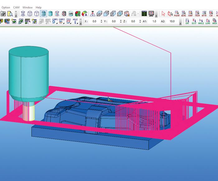
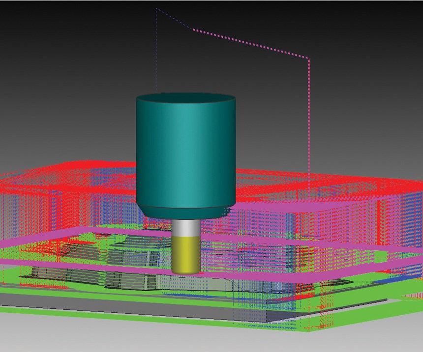
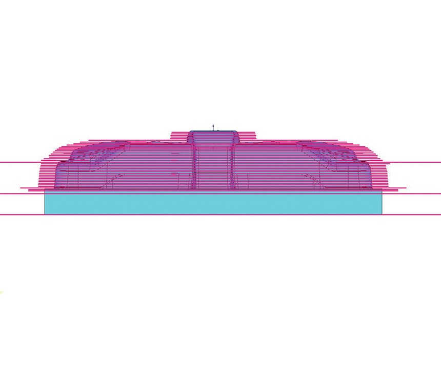
Step-up rough cutting is a roughing strategy designed to maximize metal removal rates by using the side flutes of an end mill to rough out steel. It uses large axial depths of cut and small radial depths of cut, as opposed to the small depths of cut and high feed rates of traditional high-speed roughing strategies. The tool path created by this roughing strategy constantly engages the length of the cutting flutes and steps down to the maximum recommended depth of cut.
The key to this roughing strategy is ensuring that the tool is not overloaded. This can be costly with this type of tool path, since the tools are engaged in large depths of cut, causing a tool to break more quickly. Although many CAD/CAM software companies use large depths of cut, step-up rough cutting is different, because it uses a smaller step-up amount to get closer to the net shape.
Formula for Reducing Roughing Cycle Times
To take advantage of step-up roughing to achieve the highest possible metal removal rates, you need to consider the cutting tool, machine and CAD/CAM software. They work together to reduce roughing cycle times. Using aggressive machining strategies with improved cutting tool designs and coatings makes higher feed rates possible on high-speed machines, which helps achieve higher metal removal rates in many different types of materials. This roughing strategy is particularly successful in hardened steels.
To extend tool life and make more accurate cuts throughout the roughing cycle, apply a layer of coating to the cutter flutes. Cutting tool coatings are designed to keep the shape of the cutting edge longer, which minimizes friction and keeps the temperatures more constant. Common coatings include titanium carbo-nitride (TiCN), diamond, chromium nitride (CrN), titanium aluminum nitride (TiAlN or AlTiN) and titanium carbo-nitride (TiCN).
Cutting tool designs also impact metal removal rates, so it is important to stay on top of the constantly evolving tool designs that each require specific strategies. This is where the right CAD/CAM software comes into play to ease the use of new machining strategies like step-up roughing.
Use a surface-based CAD/CAM to maintain an even stepover and maximum tool engagement throughout the whole tool path. By having the ability to limit the tool’s engagement, a much safer and more consistent tool path will result. This allows you to move faster and more freely through open areas and to keep the tool path controlled in slotted areas and corners.
When machining parts that force the tool into tight corners or slotted areas, the software will recognize this and then apply a fillet arc, or trochoidal movement, to ensure a consistent chip load. When entering tight areas, slower feed rates are applied upon reaching the maximum set-allowance for tool engagement.
One challenge with step-up rough cutting is the amount of time the tool spends cutting only at its tip, which is where you will see tool wear first. To reduce tool wear, consider a surface-based CAD/CAM that recognizes the exit motion of a trochoidal movement and raises up the cutting tool slightly in the Z direction. This keeps the tool off of the steel while still maintaining a circular movement, which in turn reduces the time the tool’s tip is on the steel. This can extend cutter life.
After the tool path has been displayed, your surface-based CAD/CAM should apply an accurate representation of the remaining stock and interference checks to the shank/head/holders. This quickly notifies the operator of any errors.
Another key aspect of effective step-up rough cutting is the machine and the controller. A machine equipped with high-speed look-ahead can have faster cycle times, because it allows the machine to keep up with the data being entered. Machines with high-speed look-ahead will also cut more accurately, because they do not have to slow down as they wait for more points. This slowdown causes the tool to spin unnecessarily on the steel.
Surface-based CAD/CAM software, which has the ability to create tool paths directly on the surface, is highly beneficial to machines equipped with high-speed look-ahead, because the software can output more points and not have to slow down to read each point in the tool path. This will increase tool life when there is no deviation from the actual displayed tool path, which provides more controlled tool engagement and a safer tool path. This is critical when applying step-up rough cutting to maintain a safe and fast roughing process.
Related Content
How a Small Programming Change Cuts Cycle Time in Half
Overriding the CAM system when milling a series of lifter pockets helps to improve metal removal rate and increase feed rates.
Read MoreTolerancing in Mold Design, Part 1: Understanding the Issues of Conventional Bilateral Tolerancing
Mold designers must understand the location, orientation and form limitations of conventional tolerancing before changing to another dimensioning system.
Read MoreHow to Manage Wall Thickness Changes in Your Mold Design
To ensure even filling and cooling, consider wall section transitions, corners and fillets, ribs and bosses, lip and rim designs and CAE flow simulation software.
Read MoreTolerancing in Mold Design, Part 2: Using GD&T to Address Conventional Tolerancing Issues
Mold designers can achieve a single interpretation of workpiece functionality when following the American Society of Mechanical Engineers Geometric Dimensioning and Tolerancing standard.
Read MoreRead Next
How to Use Strategic Planning Tools, Data to Manage the Human Side of Business
Q&A with Marion Wells, MMT EAB member and founder of Human Asset Management.
Read MoreAre You a Moldmaker Considering 3D Printing? Consider the 3D Printing Workshop at NPE2024
Presentations will cover 3D printing for mold tooling, material innovation, product development, bridge production and full-scale, high-volume additive manufacturing.
Read MoreHow to Use Continuing Education to Remain Competitive in Moldmaking
Continued training helps moldmakers make tooling decisions and properly use the latest cutting tool to efficiently machine high-quality molds.
Read More
