Software Suppliers Seek Common Platforms for Mold Development
The goal is efficient data transfer that significantly reduces mold build cycles and increases margins.
Advances in design and engineering software are improving the ability of moldmakers to reduce leadtimes and maximize productivity in many areas, notably electronics, where rapid product changeovers dominate the market. Suppliers are doing this with programs that in-crease the speed and economy of mold building.
Key areas of improvement include programs that cost-out mold designs with greater accuracy; run multiple design, engineering and simulation modules with no need for data translation; archive and update corporate mold design standards; assure that current data are accessed by different moldmaking departments; and reduce or eliminate the need for prototype molds.
Some suppliers even claim that new versions of their software help OEMs gauge the carbon footprint of a manufacturing process by detailing how part design affects mold engineering, injection machine size and material, power and transportation requirements.
Cutting Development in Half
Mold design software has always been synonymous with productivity. But suppliers are saying that new versions can decrease development cycles by 50 percent or more—a critical consideration when bidding for work in electronics, with its high part volumes and short product lifetimes.
The surge in productivity meets two critical needs of moldmakers. One is relief from the relentless cost pressure of OEMs. Software that speeds development cycles permits toolmakers to reduce the man-hours they invest in mold design, one of the few ways of improving margins that they can control. The other need is protecting business from offshore competition. A moldmaker who can take a part design, develop a mold, quote accurately for it and deliver the tool in weeks or days will guarantee an OEM a much faster time-to-market cycle than any source offshore.
Software developments also highlight an ongoing trend in moldmaking—the ability of advanced shops to build market share at the expense of toolmakers with fewer design and fabrication capabilities. Moldmakers that have upgraded operations in areas like automation, high-speed machining and now software are better positioned to compete for complex molds, a market that is generally resistant to offshore sourcing.
Simulation Compatibility
One example of software enhancement is mold-fill simulation, which is either being bundled into programs or optimized for use with them. Though mold-fill simulations are typically used as analysis tools with CAD software, their operation usually involves integrating a module with a CAD package and running it through a translator to get accurate data. A few suppliers offer purpose-designed mold-fill software that provides a seamless flow of data to and from a CAD program. This improves the accuracy of simulation data and eliminates translation.
One such is SolidWorks (Concord, MA), which has partnered with mold-fill software provider Simpoe (Torcy, France). The result is that data from Simpoe-Mold, the simulation product, can be transferred to SolidWorks’ CAD program with no loss of information or translation delays. “We have good IGES import software, but it’s always better to go native,” says Craig Therrien, Product Manager at SolidWorks, of the new capability. “Everything can be updated with one click.”
Therrien adds that with the ability to develop a mold design and then quickly test mold flow, a toolbuilder can “make modifications based on the Simpoe or SolidWorks software and iterate a design back and forth without building a mold. These systems reduce prototype tooling,” he says, “and are simple to use.”
Autodesk Inc. (San Rafael, CA) took a major step toward expanding the capabilities of its CAD software last June, when it acquired Moldflow Corp. (Framingham, MA), an iconic name in mold-fill simulation. Moldflow software will continue to support multiple vendors, but Autodesk plans to bundle it with a new tooling suite called Inventor that has been released on a selective basis.
Inventor is designed to bring products to market quickly. A key feature is ease of use, which will be enhanced by the addition of Moldflow software, says Samir Hanna, Vice President of Computer-Integrated Manufacturing at Autodesk. The Moldflow software, which can be run with current versions of Inventor, will speed mold development by seamlessly integrating and updating data between the CAD and simulation formats. “You want to come to market with the least number of prototype molds. The ease of software use by people who aren’t experts, but are looking to shorten development time as much as possible is important,” he says.
“As materials and moldmaking technologies become more sophisticated, we have to address them with more advanced analysis,” Hanna adds. Autodesk’s acquisition of Moldflow is one way the company “supports digital prototyping through the entire spectrum.”
Inventor and Moldflow software will not only give designers data about part manufacturability and economy, Hanna notes, but information that lets OEMs extrapolate the sustainability of a product during manufacturing. Once the size, weight and material of a part are determined and a mold designed for production, OEMs can calculate its carbon footprint based on press size, power requirements, transportation needs and other factors. It’s not new information by any means—many OEMs include requirements for injection press sizes in mold design specs—but its use as a way of gauging sustainability is becoming a standard feature of design and development.
Fast and Accurate Quotes
Front-end calculations of mold costs are critical to contract bids and, where OEMs are concerned, to determining if a moldmaker is overbidding or underbidding on a job. Cimatron (Novi, MI) displayed an upgrade to its CimatronE CAD/CAM software at IMTS last month that included an enhanced quote generator as part of its improvements to design automation. The quote module on the new Version 9 software does a minute analysis of a mold design to provide what Hari Sridharan, Vice President of Engineering, says is a realistic price for an injection mold or extrusion die.
The module analyzes part design, then examines aspects of a preliminary mold design like the mold base, number of splits and slides, cores and cavities, ejector pins, holes and gating positions, draft angles, and locations of a hot runner manifold, water cooling lines and venting. The quote generator also determines if the mold will work on a particular size injection press.
The resulting quote gives moldmakers a realistic price to take to an OEM, Sridharan claims. It also can be used by an OEM to determine if a price submitted during a request for quotes is an overcharge or low enough to indicate a mold shop will lose money on the job and possibly not deliver the work on time or to specifications.
He adds that the preliminary design data developed by the quote generator can serve as a basis for subsequent work on the mold. “A project manager can take the database used in understanding the part and in doing a preliminary mold design and send it to technicians who will work on the mold,” he says. Because the data are all on CimatronE, there is no need for translation by other departments. “Everyone stays focused and on the same track.”
Smooth data transfer can dramatically reduce mold design cycles. Sridharan says that it’s not unusual for moldmakers to spend 15 to 20 percent of mold design time translating data. “Even if a moldmaker shaves 5 percent of that off the mold building cycle, it’s a critical saving in time and cost.”
Cimatron also has upgraded the NC programming in its CAM software with enhanced algorithms controlling knowledge of remaining stock and rest machining. Claimed benefits include reduced calculation time during programming, faster machining and improved surface quality.
In one area that’s key to electronics design, upgrading products, Delcam (Windsor, ON) has a new version of its PowerSHAPE CAD software that features “tribrid modeling.” The name derives from the addition of a third function, triangle modeling, to surface and solid modeling functions. Combining them will reportedly speed reverse engineering and permit faster development of product improvements, bespoke designs and new products that are variations of earlier versions. Delcam achieves tribrid modeling by integrating its CopyCAD reverse engineering and triangle modeling software into the hybrid-modeling version of PowerSHAPE Pro.
The product is slated for introduction later this month at the TCT rapid product development expo in Coventry, England.
Upgrading Design Archives
Dassault Systems uses a technique it calls realistic simulation to develop mold designs with Catia software that can be proved without prototypes. Mike Ray, Senior Application Engineer at Dassault Systems (Lowell, MA), whose products include Catia software, says this is done with a feature called Mold Tooling Design Workbench that lets moldmakers add corporate design standards to a database, which can be automatically updated to meet changing specifications.
The database is a catalog of mold designs. A mold shop—or OEM—inputs its institutional knowledge about which components and designs work best in molds for different products and accesses them, along with items from standard catalogs of components, when designing for similar applications. The dimensions and positions of components and the size of a mold base can, for example, be automatically changed to meet new specifications. The basic design of a new mold, however, builds off what’s been proven to work as shown in the catalog.
Catia has had the feature for several years, but recently released what Ray calls a more robust version that’s largely based on customer feedback. He claims that with it a moldmaker can take a complex part and develop virtual tooling for it in a day or two. The mold shop can calculate an accurate price and submit a bid to an OEM soon after.
“People who do complex designs are interested in this,” Ray says. “In the past tools were difficult to customize. But with the design catalog and automatic upgrade capability, a moldmaker can pick-and-click the modifications he wants. It’s simple to do.”
One other point Ray makes is that the Mold Tooling Design Workbench lets companies record the design and fabrication knowledge of veteran toolmakers. If they retire from a company or change jobs, their expertise remains.
Summary
The capabilities of design, manufacturing and simulation software are rapidly being upgraded. Moldmakers must pay as much attention to these advances as to machining and automation enhancements, if they want to maintain leading-edge capabilities in a time-critical and cost-sensitive market like electronics.
|
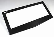
Heat/Cool Molds Yield Glossy Parts The process, thermal cycling of molds, creates a high-gloss finish on parts, reduces molded-in stress and eliminates weld lines and parting lines. The technique isn’t new—thermal cycling has been around since the 1980s. But work is ongoing to improve its commercial potential. Sabic Innovative Plastics (Pittsfield, MA) is fine-tuning the process, which is used by 30 to 40 molders in Asia-Pacific, some making electronics parts, says Project Engineer Andy May. One application is television bezels, where thermal cycling eliminates painting and other finishing operations. A mold surface is heated 10 to 30°C above a resin’s glass-transition (Tg) temperature. The maximum is about 200°C, so the process isn’t for high-temperature polymers. Heating is by steam or superheated water, which circulates through a mold from an external boiler or press-side unit. Raising mold surface temperature prevents a skin-like surface forming on a part when polymer is injected. “Without the skin there is more intermingling of polymer chains across the knit line,” May says. This eliminates the appearance of knit lines and encapsulates glass-fiber reinforcements, rendering them invisible. The technique also replicates a mold surface on a part. “If it’s a high-polished surface, you can achieve high gloss levels on the part and duplicate surface features down to a micron level.” After injection the mold is rapidly cooled with water prior to demolding. The process increases cycle time, typically 30 to 50 percent, Mays says, though this is offset by elimination of secondary operations. Thermal cycling can be retrofit to molds depending on part size and tool design. It is probably best with new molds built for the process. The system can be used with conventional tool steel interspersed with high-thermal-conductivity metals. May says mold mass should be reduced to improve thermal cycling, and as a result, cores and cavities need to be inserted rather than built in and insulated to minimize heat loss. At least three companies supply the thermal equipment: Single Temperature Controls (Charlotte, NC), Sysko Corp. (Soka City, Japan) and Unibell Co. Ltd. (Siheung-Si, Gyeonggi-Do, South Korea). |
Related Content
Mold Design Review: The Complete Checklist
Gerardo (Jerry) Miranda III, former global tooling manager for Oakley sunglasses, reshares his complete mold design checklist, an essential part of the product time and cost-to-market process.
Read MoreHow to Improve Your Current Efficiency Rate
An alternative approach to taking on more EDM-intensive work when technology and personnel investment is not an option.
Read MoreThree Good Reasons to Switch from Three- to Five-Axis Machining in Moldmaking
Five-axis machining technology is a great tool in the moldmaker toolbox.
Read MoreWhat is Scientific Maintenance? Part 2
Part two of this three-part series explains specific data that toolrooms must collect, analyze and use to truly advance to a scientific maintenance culture where you can measure real data and drive decisions.
Read MoreRead Next
Choosing CAD Software For 3D Mold Design
The world of CAD offers many alternatives to shops that want to use the latest 3-D technology for their mold design. This article looks at the benefits of the various approaches and offers some tips on choosing the most appropriate one.
Read MoreHow to Use Continuing Education to Remain Competitive in Moldmaking
Continued training helps moldmakers make tooling decisions and properly use the latest cutting tool to efficiently machine high-quality molds.
Read MoreHow to Use Strategic Planning Tools, Data to Manage the Human Side of Business
Q&A with Marion Wells, MMT EAB member and founder of Human Asset Management.
Read More


