Software Package Increases Solid Modeling Capabilities
Moldmaker streamlines its operations with new software - cutting design time in half.
Located in Erie, PA, F&S Tool serves the medical, consumer products, automotive connectors and closure industries - building molds from single-cavity up to 128-cavity molds, including stack molds. During the 18 years it has been in business, the company has been looking for the best software to meet its diverse needs and maintain optimum efficiency.
According to J.D. Faulkner, vice president of F&S Tool, when he needed to expand his NC programming operation, a local distributor suggested the company try VISI-Series - a suite of applications for moldmakers that is based on a solid modeling CAD technology. The system was developed by Vero International (Detroit, MI) - an international developer of engineering CAD/CAM software for toolmakers and machinists - and includes functionality for modeling, design and machining.
"Initially, we wanted to enhance our capabilities by adding solid modeling technologies to our realm of 3-D machining and design applications," Faulkner says. "We installed the package on a trial basis to evaluate its performance against our current methods of modeling and manufacturing. We quickly realized the strengths of the software and began to integrate it into our production operation as part of our ongoing process of technological advancement."
The Original Project
Faulkner notes that the original software test project focused on the modeling and production of electrodes for the company's EDM applications. The method they had been using was built entirely upon surface-based CAD systems. "The majority of our customers would provide us with IGES files of their product," he explains. "Traditionally, we read customer files into our software, located the necessary geometry to develop an electrode, and then extracted it to a separate file to develop the particular electrode model.
"The previous concept was simple: save as much time as possible by utilizing the database in its original format," Faulkner continues. "This meant keeping the part geometry as individual surfaces and manipulating them as required."
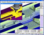
The new concept to be evaluated was built on the VISI-Series product and involved the use of a solid modeling front end and the machining of solid models. More specifically, Faulkner wanted to know if it was feasible to "waste time" in the initial engineering process of generating a solid part model (by converting, fixing and sometimes recreating IGES surface data) and then come out "ahead of the game" in the machining process with increased overall production efficiency.
"The benefits of having solid models for engineering purposes were evident - part definition problems and engineering changes can be rapidly resolved," Faulkner explains. "But the engineering issues regarding model generation time and the manufacturing issues of speed, productivity and product quality in a 'solids'-based environment remained a mystery."
Once the software was put to use, the answers became clear - not only were the initial benefits in engineering realized, an additional benefit was realized when it became dramatically easier to create electrode models that were corrected for overburn. Compared to their traditional surface-based system, the VISI-Series solid modeler was significantly easier, Faulkner notes, and reached the bottom line with timesavings.
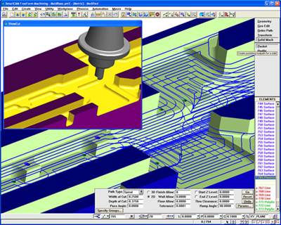
Additional savings were realized in manufacturing, according to Faulkner. Collisions could be quickly analyzed and avoided because the toolpaths were developed on solid models. "Our programmers were able to more confidently visualize and assess the aspects of a complicated 3-D toolpath in a 3-D solid model than on a surface model where you must keep track of things like surface direction and surface edges where tools can fall off and gouge," he comments. "Solids enable a user to work in an environment that is inherently obvious."
Additional Exploration
The initial success of his NC software expansion project led Faulkner to consider the replacement of his previously installed software and ask himself some hard questions. "Was our other software offering functionality beyond that in VISI-Series? What are the shortcomings of the VISI-Series that would limit our functionality if we choose to move our whole operation to the new program?" F&S spent the next two years assessing and refining their original decision as they gradually moved more of their operations into the VISI-Series software operation. "We now use VISI-Modeling extensively for design and find that it is usually faster at our modeling and concept work in our rapid prototyping operation," Faulkner notes. "Even if we need to design and model an entire mold, we've found it goes more quickly in VISI. Once done, we are able to begin immediately machining the parts from the solid models before the prints have been made. According to the old school of thought, this was considered dangerous, but the modern demands of industry force us to push our technology further and find better solutions."
The company now manages its business considering productivity per NC programmer. "We have found that with VISI-Series software, we are able to have one programmer maintain a constant flow of work to two carbon mills," Faulkner states. "This may not sound impressive at first, until you understand that these machines are attached to robotic part changers that enable them to run 24 hours per day non-stop. What this means is that what a programmer accomplishes in one shift must keep two machines busy for three shifts. What complicates this issue is our typical mix of jobs. We deal with a high volume of short run programs where we machine a small number of parts per program. In short, we needed to couple the productivity of robotic part changers with a faster NC programming operation - everything needed to run faster.
"This is the pace," Faulkner adds, "that we must maintain at F&S to remain competitive. The painful truth is that customers don't take time to consider whether you can keep up with their demands - they just expect it."
F&S Tool currently operates on six licenses of VISI-Series software - one VISI-Modeling seat strictly for modeling and designing, and the other five seats include both VISI-Modeling and VISI-Machining to support its milling applications. One of the five is dedicated to electrode production, two are dedicated to mold base production, and two are dedicated to mold component production. The five seats are spread between seven programmers over two shifts. "Occasionally we find a seat not being used, but for the most part they are always busy," Faulkner says.
The Results Are In
"Any tool shop looking at a new piece of equipment will always insist on knowing the metrics of the purchase - accuracy, tolerances, throughput and reliability," Faulkner says. "The purchase of NC programming software should be no different. Because all work does not require the same accuracy, you need to confirm that your software will meet all of your needs. For example, on electrodes, it is typical to hold a .0002 tolerance on a shutoff surface. But on a roughed component of a mold, more generous tolerances are allowed for speed of machining and programming. This software has worked well for us in all of these regards, and we like the versatility of being able to apply precision tolerances to rough cuts as well as finish cuts when a situation demands it.
"Don't forget to evaluate software alternatives with consideration for the personnel involved," Faulkner continues. "Remember that your software package is a tool - it can only be as accurate and useful as the experience and knowledge of the user."
While Faulkner believes it is rare to find a CAD/CAM system that will solve all imaginable problems, he realizes that VISI is a powerful programming package that can make toolmaking operation more productive and easier to run. It streamlined F&S Tool's operations by providing an exceptionally good solid modeling environment integrated with machining of solids. "This software generated complex cutter paths for free form geometry and yet was easy to learn," he says. "The learning curve was minimal compared to other packages of its kind, and we have found the system compatible with every other system we have attempted to integrate with it. We have come to rely on it as the backbone of our CAD/CAM functions."
Related Content
True Five-Axis Machine Yields More Throughput, Greater Productivity
CDM Tool & Mfg. Co. LLC increased shop capacity thanks to a versatile high-speed/high-accuracy five-axis Fooke mill capable of cutting very large workpieces quickly and accurately with fewer setups.
Read MoreLaser Welder Yields Fast, Precise Mold Repair
Intralox's integration of the Alpha Laser ALFlak has significantly improved their tool room efficiency when it comes to difficult welds and urgent repairs.
Read MoreHybrid Milling/Drilling Machine Reduces Total Mold Machining Time
MSI Mold Builders now squares, plus drills and taps eye-bolt holes on 50% of its tools in a single setup using a five-axis milling/drilling center with a universal spindle.
Read MoreCAD/CAM Software Reduces Delivery Times by 70% With a Six-Month ROI
Single integrated CAD/CAM package reduces translation errors, simplifies design process, improves shop efficiency and shortens tool lead times.
Read MoreRead Next
Generate Toolpaths Directly From Solid Models
SmartCAM V16. 0 from SmartCAMcnc includes automated toolpath generation directly from a solid model, additional solid model translation and improvements in visualization, verification and usability.
Read MoreReasons to Use Fiber Lasers for Mold Cleaning
Fiber lasers offer a simplicity, speed, control and portability, minimizing mold cleaning risks.
Read MoreAre You a Moldmaker Considering 3D Printing? Consider the 3D Printing Workshop at NPE2024
Presentations will cover 3D printing for mold tooling, material innovation, product development, bridge production and full-scale, high-volume additive manufacturing.
Read More
