Six Key Factors for Evaluating a Hot Runner System
Details matter when it comes to selecting and integrating a hot runner system. This guide makes that process easier by covering those details thoroughly.
Mold builders and injection molders have different requirements when it comes to hot runner systems. Mold builders are often concerned about price, delivery and quality, while the molder is concerned with operation, performance and ease of maintenance. However, both moldmaker and molder must be part of the decision-making process when considering a hot runner system and supplier to guarantee the best selection from available system options and to optimize integration of the system into the mold.
Here are six important items to consider when evaluating a hot runner system:
1. Manifold heaters. For installation, most manufacturers use a press. If the heater contact with the manifold is not uniform, there will be hot spots created in the heater element, which causes premature failure and non-uniform heating of the manifold itself. Also, process capability can be affected especially with some engineering materials, as their viscosity may be more temperature sensitive than commodity resins like polypropylene and polyethylene.
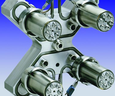
Image 1. This four-drop hot runner system has pressed-in tubular heaters. Photo courtesy of Incoe Corp.
2. Nozzle heaters. Measuring the ohm resistance for each nozzle heater can provide good information when troubleshooting the hot runner system. Too great a variance may prevent uniform temperature profiles and the potential for process variation will increase. Additionally, the life of a heater with less efficiency is reduced because of the required increase in workload.
3. Nozzle tip orifice. Pressure differences in plastic injection molding are defined in the Hagen Poiseuille equation, where (Q) is the flow rate, (l) is the runner length, (n) is the material viscosity and (r) is the radius of the flow channel: ∆P=(8Qln)/(πr4)
The equation shows that any slight difference in “r” value, which includes the orifice in a hot runner nozzle and gate tip, is affected to a magnitude of the fourth power. This means that a small change in radius will result in a rather large difference in pressure drop from gate tip to gate tip. The common perception is that if the gate tips are all within tolerance, this will not matter. However, it is important to ask what the acceptable tolerance is along with the gate tip dimensions. Just because they are within tolerance does not mean there will not be a difference in pressure drop.
For example, a tolerance of +/- 0.002 inches on a gate diameter of 0.300 inches may be too large of a tolerance range to achieve consistent molding. Of course, a processor may adjust individual tip temperatures to try overcoming some of these variations. It is
important to understand that by doing this, the processor is changing the material conditions from which the parts are being molded. If the processor runs semi-crystalline materials, then he or she may create further issues with crystallinity differences near the gate versus other areas of the part.
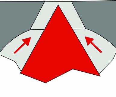
Figure 1a. This image shows the location after additional thermal expansion. Notice the effective flow channel is less here. Images courtesy of Beaumont Technologies and the AIM Instititute.
Additionally, the resultant variations in thermal expansion of nozzle and manifold steel that occur because of different temperature settings could ultimately lead to other filling variations, leaking or breakage issues. For example, if a cavity is filling behind other cavities, a processor may increase the temperature of the nozzle feeding that cavity. However, that temperature increase could drive the gate tip further into the gate orifice because of additional thermal expansion. This reduces the effective radius (r), ultimately restricts the flow and counteracts the intent of the temperature increase (see Figures 1ab).
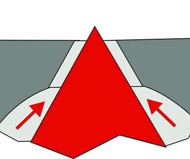
Figure 1b. The hot tip's natural position with expected thermal expansion. Images courtesy of Beaumont Technologies and the AIM Instititute.
It is also important to understand that raising local nozzle or manifold temperatures may cause an increase in cycle time since the material and mold in that region will stay hotter for a longer period.
4. Stack height. It is important to check the uniformity of the stack height across all nozzle tips (see Figure 2). If these dimensions vary, then the engagement with the gate will also vary, and these variances could affect process capability because of resulting differences in channel geometry. Ask for the inspection report and consult the manifold supplier for an acceptable tolerance. Revisit the pressure drop equation to see if the tolerance that the supplier provides is acceptable for a given process and set of parts.
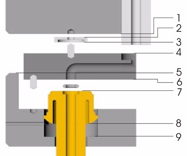
Figure 2. Checking the uniformity of the stack height across all nozzle tips is important to avoid points of tolerance stack-up issues shown here. Images courtesy of Beaumont Technologies and the AIM Instititute.
5. Flow channels. All gun drill manufacturers will claim variances of 0.001 inch per inch of travel. Check that they can verify that the cross drilling of the flow channels does not leave a step at the intersection of the cross-drilled runners. Refer to the earlier equation again. Check that the gun drill manufacturer scoped and honed the channels. Variations in flow channels could create differences in pressure drop through the regions of a manifold. Again, this refers to the portion of the equation involving the radius (r), which is raised to the fourth power.
Steps in the flow channel can create dead spots, which do not flush well when purging and cause color-change issues and material-degradation problems. Also, the steps make it possible for material to sit in the manifold for extended periods, which increases the likelihood for thermal degradation of the polymer.

Figure 3. The natural flow path of the polymer through a branched runner and around a corner is shown in red. Potential stagnant locations are indicated in blue. Images courtesy of Beaumont Technologies and the AIM Instititute.
The polymer’s natural flow path around the channel intersections also causes these dead areas. This happens even if the channel intersections are perfectly aligned (see Figure 3).
6. System cost. The cost of the system is often one of the most important things to consider, but relying solely on quotes from various suppliers is not the best way to approach the issue. Familiarity with the various options each hot runner supplier offers is helpful. For example, some suppliers may provide the ability to separate the manifold from the mold while the mold is still in the molding machine, reducing maintenance and downtime. Another thing to think about is how the channels are manufactured. The manufacturing method may affect color changes and require additional clean-out procedures that expand on traditional purging approaches. (See the sidebar for a list of common direct and indirect costs when evaluating the overall system.)
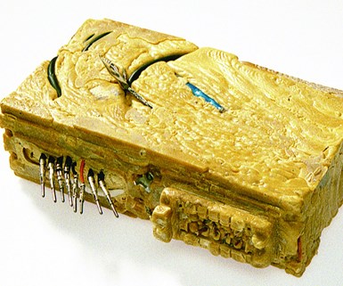
Figure 4. This leaking manifold caused plastic to encase the hot runner wiring. Images courtesy of Beaumont Technologies and the AIM Instititute.
It is often said that the devil is in the details, and this certainly applies to hot runner system evaluation and performance. Issues arise, so it is important to be aware of some common challenges and potential sources of variation, including high pressures at assembly points, co-existence with a cold mold and platens, gating issues (cooling, clogging, drooling, stringing), processor skill level, shot size, residence time, leaking (see Figure 4), valve pin seating, shear flow imbalances, power consumption and thermocouple placement and contact.
Making a more informed decision requires a thorough understanding of the hot runner system’s design, manufacturing process and available options. It also requires a solid understanding of troubleshooting and mold qualification standards. Staying on top of the items described in this article will reduce downtime, improve part quality and decrease overall costs.
About the Contributors
David Hoffman and John Blundy
David Hoffman is a senior instructor and development manager for plastics education and training for the American Injection Molding Institute (AIM). John Blundy also contributed to this piece when he served as vice president of business development at Beaumont Technologies, Inc..
Other key hot runner articles:
Breaking Down Hot Runner Maintenance
Switch to Hot Runners Pays Off for Pulley Molder
Why Choose a Valve-Gated Hot Runner?
Related Content
Hands-on Workshop Teaches Mold Maintenance Process
Intensive workshop teaches the process of mold maintenance to help put an end to the firefighting culture of many toolrooms.
Read MoreFundamentals of Designing the Optimal Cooling System
The right mold components can help improve mold cooling and thereby produce higher-quality parts.
Read MoreHow to Eliminate Chatter
Here are techniques commonly used to combat chatter and guidelines to establish a foundation for optimizing the moldmaking process.
Read MoreRead Next
Switch to Hot Runners Pays Off for Pulley Molder
Retlaw has cut scrap, improved part quality and slashed cycles since adopting hot runner technology.
Read MoreBreaking Down Hot Runner Maintenance
Improving a manifold’s maintenance plan requires specific skills and knowledge of its functioning areas.
Read MoreHow to Use Continuing Education to Remain Competitive in Moldmaking
Continued training helps moldmakers make tooling decisions and properly use the latest cutting tool to efficiently machine high-quality molds.
Read More
