Save Time and Money with CAD Animation
Using CAD animation can save potential, and often unnecessary, mold design costs.
Using CAD animation can save potential, and often unnecessary, mold design costs. It’s much easier to fix virtual molds than it is to repair physical molds, and that’s where CAD animation can help.
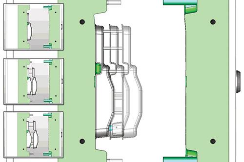
Many companies don’t use animation when validating mold designs, however, and if they do, oftentimes they rely too heavily on 2D and 3D still images, which can’t completely capture travel movements. For example, when a moldmaker uses a 2D image to show the mold in travel position, it is difficult to see what has occurred at the front and back of the travel section and to the mold design during travel. The 2D still image simply doesn’t capture all travel movements as CAD animation does. Plus, mold designs may need to be manually updated when a change is made.
Showing the mold travel position in 3D allows one to see what is in the front and back of the travel section, but it still does not show what happened during travel, and again, mold design changes will need to be manually updated. On top of that, the extra data stored in the design file can also dramatically increase the job’s file size, causing other delay and cost concerns.
CAD animation can be used before a physical mold is made to help determine if all the mold components function correctly. Here are four areas where CAD animation makes sense:
1. Mold opening. CAD animation can verify that the mold opening meets press specifications. If not, the mold design can easily be adjusted and the animation re-run.
2. Part ejection. Animation can check part ejection. The operator can use it to verify that clearance is acceptable, that the part free-falls and/or that the robot has room to maneuver.
3. Lifter travel. CAD animation can be used to validate lifter travel. Do the lifters clear the part undercut? Do the lifters interfere with the part during travel? Is there sufficient lifter acceleration or deceleration? Do the lifters hit each other or other components? Are undercuts in the direction of the lifter draw? Do lifters hit phantom steel (or areas where the lifter clears plastic, but hits steel)? If any of these issues are detected, the mold design can easily be updated before the physical mold is created.
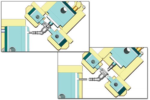
4. Slide travel. Animation can be run for slide travel validation. This will verify that slides clear the part and whether there are undercuts in the direction of the slide draw, and will ensure that there are no slide collision (including water fittings).
CAD animation can help reduce mold repair and redesign costs, manufacturing delays, and embarrassing results at customer tryouts. Do it right the first time, and save time and money by making CAD animation part of your mold design process.
Synergetic Eng. Inc. / Innovative Solutions
Related Content
-
How to Fix Predicted Warpage Before It Happens with Windage and CAD Model Morphing
Applying windage and model-morphing techniques saved toolmaker/molder Sturgis Molded Products the time, cost, headaches of multiple part/mold design iteration loops, cumbersome cooling fixtures, and long molding cycles.
-
How to Improve Your Current Efficiency Rate
An alternative approach to taking on more EDM-intensive work when technology and personnel investment is not an option.
-
Tips for Tackling Mold Design, Machining, Cutting Tool and Wear Challenges
Tips for tasks ranging from reducing risk in part design and taking advantage of five-axis machining to refining cutting tool performance and reducing wear with guiding and centering systems.


