Reducing Risk in Lights-Out Machining
Surface-based CAM software can increase accuracy and make unattended machining a possibility for shops that have avoided it in the past.
Lights-out machining is a term used in manufacturing to describe unattended machining or machining after everyone has gone home for the day. As timelines continue to get shorter and labor remains a large part of the mold-building process, this is a very attractive concept for shops, financially. Technological advancements such as toolchangers, lasers for tool pickup, and improved cutting tools, holders and machines have made this type of operation much more feasible now than it had been in the past.
Some shops still consider lights-out machining to be an uncertain operation, however. The risk of a cutting tool failing or incorrect programming with no one in the shop to stop the machine could result in a very costly mistake. Advancements in CAM software have greatly reduced these risks, however, making it possible for shops to run lights-out without worrying about returning to broken cutters, scrapped parts or damaged spindles the next morning.
CAM software is perhaps the most commonly overlooked consideration in machining, maybe because people assume it is all the same and that the software that can generate the NC code the easiest is the best. However, this is not the case. All NC code is not created equal. The methods for calculating NC code vary.
CAM Calculation
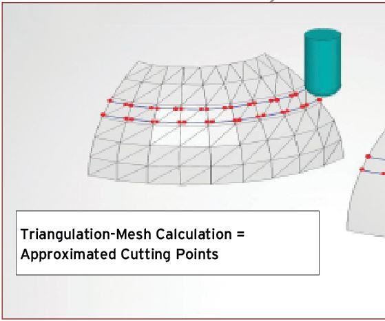
There are two types of CAM calculation: triangulation-mesh-based CAM calculation and surface-based CAM calculation. Triangulation-mesh-based CAM calculation entails laying a mesh made of triangles over the geometry and using the intersection points to create the NC code. Surface-based CAM calculation projects the points directly on the surface of the part to create the NC code (see Figure 1).
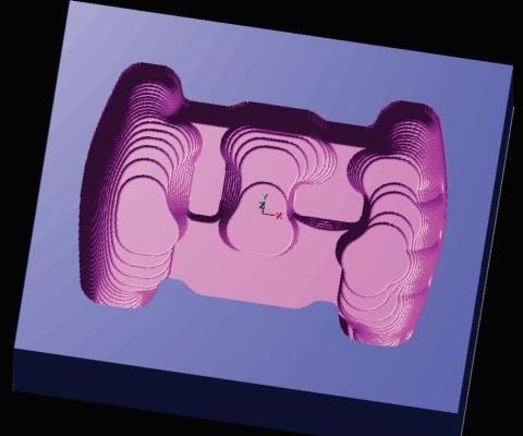
Originally, all CAM systems were surface-based, but before such systems were capable of creating virtual stock models of workpieces on the computer screen (see Figure 2), programmers had to look at the actual workpiece at the machine and generate a program quickly to keep the machine running. Calculation time became an issue, so many CAM suppliers transitioned to triangulation-mesh-based CAM to get faster calculations. Accuracy was not as important at this time, as machines were not capable of machining within the tight tolerances that they can today. Triangulation-mesh-based CAM could produce NC code faster in order to get the machines running again, but the NC code was less accurate, because the calculations produced approximate cutting points. This calculation method results in inconsistent tool paths, which can be problematic while machining lights-out. It also produces less accurate parts that require more handworking and polishing.
As CAM software functionality increased and the creation of virtual stock models made it no longer necessary for programmers to constantly look at the workpiece, shops started to move programming off the shop floor and into cleaner, climate-controlled offices. Shops began to realize that triangulation-mesh-based software was not providing the required accuracy, as inconsistent tool paths hitting unexpected stock often caused costly mistakes when machines ran unattended. Also, as computing power increased and allowed programs to be calculated much faster, the gap between triangulation-mesh-based and surface-based calculation time closed significantly.
With the development of high-speed machines, and advances in machine tool and cutting tool technology, CAM software accuracy has become more important than ever. Shops are now able to machine to tolerances that were impossible in the past. More accurate programming also allows machining of deeper areas with greater tool length-to-diameter ratios that previously would have required EDM. Also, any variation in tool paths increases tool wear, which causes major issues during lights-out machining, especially for shops using difficult-to-machine materials. Typically, tool life is increased by about 20 percent through use of a higher accuracy surface-based CAM software, which also helps reduce handwork and spotting time.
CAM Functions
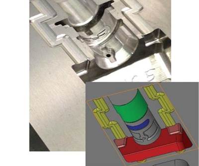
Keeping tools from becoming overloaded is essential for successful lights-out machining. Overloading causes chipping or breaking, so tool overload avoidance is a factor shops should consider in selecting CAM software. Adding a radius into sharp or tight corners in the geometry during roughing can protect the cutting tool from being overloaded in corners (see Figure 3), and adding trochoidal passes to ensure even chip load in slotted or deep corner areas can prevent overload in these situations.
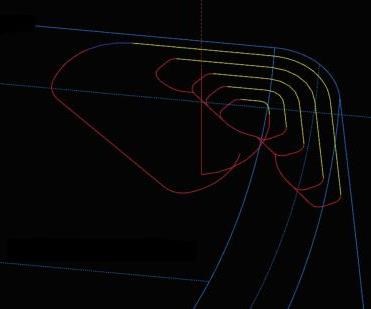
In addition to the increased accuracy and therefore decreased tool wear provided by a surface-based calculation, use of a stock model also helps prevent tool overload. This is one of the most important functions of CAM software in that it recognizes extra stock and adds extra passes to eliminate the risk of the tool breaking from hitting unexpected stock (see Figure 4).
Collision checking is another essential CAM function. It should automatically identify the exact tool length required, preventing the cutting tool or holder from interfering with the part or stock on the part. This also encourages the use of short, rigid tools that help increase machining efficiency. The key is collision checking to both the stock model and finished part. Collision checking the finished model does not account for extra stock that has not been machined yet and could lead to a major collision in that areas. Also, when machining in deep areas with little draft, a little extra stock on the wall can cause holders to rub. This will not be caught by collision checking the finished model only.
Machine simulation is another essential CAM function, and it is used frequently in five-axis machining. This simulation should include a full 3D model of the machine and then import the part geometry to ensure that the cutting tools or part do not collide with the sheet metal, covers, lasers or any other part of the machine.
When selecting your next CAM software, consider an integrated surface-based calculation solution with the functions discussed here. Together, they provide more -accurate tool paths, which should increase cutting tool life and yield safer, more successful lights-out machining.
Related Content
It Starts With the Part: A Plastic Part Checklist Ensures Good Mold Design
All successful mold build projects start with examining the part to be molded to ensure it is moldable and will meet the customers' production objectives.
Read MoreTolerancing in Mold Design, Part 1: Understanding the Issues of Conventional Bilateral Tolerancing
Mold designers must understand the location, orientation and form limitations of conventional tolerancing before changing to another dimensioning system.
Read MoreTolerancing in Mold Design, Part 2: Using GD&T to Address Conventional Tolerancing Issues
Mold designers can achieve a single interpretation of workpiece functionality when following the American Society of Mechanical Engineers Geometric Dimensioning and Tolerancing standard.
Read MoreWhat Is Scientific Maintenance? Part 1
Part one of this three-part series explains how to create a scientific maintenance plan based on a toolroom’s current data collection and usage.
Read MoreRead Next
High Accuracy and Efficiency CAM System Speeds Mold Building
The ability to machine smaller details into molds has reduced or often even eliminated the need for secondary surface finish operations.
Read MoreReasons to Use Fiber Lasers for Mold Cleaning
Fiber lasers offer a simplicity, speed, control and portability, minimizing mold cleaning risks.
Read MoreAre You a Moldmaker Considering 3D Printing? Consider the 3D Printing Workshop at NPE2024
Presentations will cover 3D printing for mold tooling, material innovation, product development, bridge production and full-scale, high-volume additive manufacturing.
Read More
