High Accuracy and Efficiency CAM System Speeds Mold Building
The ability to machine smaller details into molds has reduced or often even eliminated the need for secondary surface finish operations.
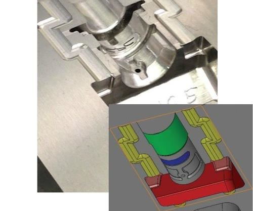
Accuracy is paramount when machining molds, and as automated as machining has become, it often still makes necessary an array of less-efficient secondary operations and handwork to achieve the geometry and surface finish required to meet product design specifications. This is especially true when a design calls for ribs and other tight-detail areas that a tool path must navigate.
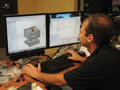
Jason Alsleben, a mold designer and toolmaker for Unique Tool Inc. in Hutchinson, Minnesota, was well-versed in the multi-step process for achieving accurate tool paths and proper surface finishes when that became unnecessary with the company’s switch to CG CAM-Tool, part of the CG Series of 3D CAD/CAM systems for molds and dies from CGS North America Inc.
Unique specializes in building small, intricate molds for medical applications such as over-molding electrical connectors and fluid connectors. The mold designs range from one to eight cavities, including master unit die (MUD) units and small, self-contained tools. For Alsleben, making the switch to CG CAM-Tool was a big step toward simplifying machining operations.
“We used another CAM system for several years,” he says. “Surface finish was always an issue, and with small end mills, tool breakage was common. Since we switched to CG CAM-Tool, having the ability to machine smaller details into our molds has reduced or often even eliminated the need to machine electrodes and burn these details into our molds. The tool paths are so precise and the surface finish is so good that we can almost eliminate the slow and costly EDM process, and as a result reduce the hours it takes to build our molds by as much as a third.”
Accurate and Safe
According to Gerry Byykkonen, Unique’s technical sales representative at CGS, the CAM software creates toolpath points directly on the surfaces to be machined versus using a not-so-exact triangulation mesh. When toolpath data is created using the true surfaces of the model, the software can generate many more points of contact between the cutting tool and the model, he says. This increased point data results in a smoother tool path that follows the surfaces to be machined with greater accuracy.
“Other CAM products place the mesh over the entire part and use this to create the tool paths,” Byykkonen explains. “The problem is, those toolpath points are not generated as accurately, and they inevitably lead to inaccuracies in the machined surfaces, including a subpar surface finish and premature tool failure.”
Alsleben concurs. “CG CAM-Tool has been extremely accurate in its tool paths,” he says. “Where using another software’s triangulation mesh only gives us an approximate surface and tool path, CG CAM-Tool shows us exactly where the tool path is and verifies it. There’s virtually no need to use the sinker EDM because we get what we need using CG CAM-Tool. It’s pretty much one and done.”
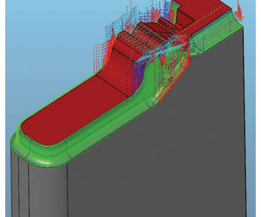
Data used to generate tool paths in the software are processed directly within the program. After calculation and verification, a color system indicates the status of the tool path: Green indicates that a correct and safe tool path has been generated, yellow indicates a potential problem that should be addressed, and red indicates a serious problem that prevents the software from outputting the toolpath program.
Alsleben says he also appreciates that the system generates a new stock model with each tool path that accurately represents the stock remaining from the previous tool, a feature not found in most other CAM software. By doing this, it enables users to accurately verify if there are any interferences between the cutting tool and holder, and the part being machined. This accurate verification also greatly reduces the possibility of costly machining errors.
CG CAM-Tool’s “delete air-cut” function helps Alsleben’s programs work more efficiently, too, he says. “After I do the initial roughing, I can replace the first end mill with a smaller one and avoid cutting air all the way down. CG CAM-Tool knows the material is out of there and doesn’t waste time getting to work. This software works really well for Z-level roughing, especially when following a larger end mill.”
As for lights-out machining without worry, Alsleben says he sleeps peacefully. “I feel much safer about the tool path I’m putting out because of the accurate verification,” he says. “When I write the tool path, I know the cutters are going to work correctly. When I walk out the door at night and machines are running, I’m not scared about walking back in on any disaster the next morning.”
Ease of Programming
Alsleben has extensive experience using SolidWorks software programs, and since CG CAM-Tool is designed to run within the SolidWorks platform, he says the learning curve was greatly reduced, as were the steps required to program tool paths.
“I don’t have to make an IGES or STEP file to translate into the CAM software, because it’s already standard within the system,” he says. “It simplifies so many things.
“Programming is much easier with the user interface in CG CAM-Tool,” he continues. “To machine a part, I simply start a new project, add tools from the machining template, define where I want each tool to cut, and then calculate. It makes cutting even the most complex parts just that easy.”
In addition, if any revisions to an existing tool path are necessary down the road, Alsleben doesn’t have to recreate the entire project. For example, if a diameter or radius change is needed, or a detail is added to the design, the project parameters are already integrated in the software, and the updates can be made automatically by regenerating the tool path. “It is so simple that it reads like a book,” he says. “You can see exactly what you did at any point within the program.”
While no two mold jobs are exactly alike, Alsleben does find added convenience in CG CAM-Tool’s ability to use previously programmed toolpath templates to save time on future jobs. For example, it may take half an hour to program the process for squaring up a new block for a set of mold bases from scratch, but the saved templates can be used to program a similar future job in just a few minutes.
“When I have multiple projects in the queue, CG CAM-Tool lets me continue programming while other parts of a program are calculating,” Alsleben adds. “I’m not wasting time waiting for toolpath verifications that could take several minutes to calculate. It’s efficient. It’s fast. It’s very accurate. It has really advanced the way we build molds.”
Related Content
Tips for Tackling Mold Design, Machining, Cutting Tool and Wear Challenges
Tips for tasks ranging from reducing risk in part design and taking advantage of five-axis machining to refining cutting tool performance and reducing wear with guiding and centering systems.
Read MoreTolerancing in Mold Design, Part 1: Understanding the Issues of Conventional Bilateral Tolerancing
Mold designers must understand the location, orientation and form limitations of conventional tolerancing before changing to another dimensioning system.
Read MoreHow to Manage Wall Thickness Changes in Your Mold Design
To ensure even filling and cooling, consider wall section transitions, corners and fillets, ribs and bosses, lip and rim designs and CAE flow simulation software.
Read MoreThree Good Reasons to Switch from Three- to Five-Axis Machining in Moldmaking
Five-axis machining technology is a great tool in the moldmaker toolbox.
Read MoreRead Next
Redefining CAM Technology for Moldmakers
Tool paths that dynamically adjust tool motion allow faster, safer machining without the need for high-speed equipment.
Read MoreReasons to Use Fiber Lasers for Mold Cleaning
Fiber lasers offer a simplicity, speed, control and portability, minimizing mold cleaning risks.
Read MoreHow to Use Strategic Planning Tools, Data to Manage the Human Side of Business
Q&A with Marion Wells, MMT EAB member and founder of Human Asset Management.
Read More


.jpg;maxWidth=300;quality=90)


