Part Two of a Three-Part Series Five Steps for Improving Your Shop’s Maximum Productivity Part 2
The reasons and justification behind moving your component finishing operation from EDM sinking to hard milling with the right machine, software, cutters, toolholders and training; and how you can add machine time to your shop through lights out machining.
Share
Part II of this series will examine two of the five principles for improving your shop’s maximum productivity: (1) why and how to move your component finishing to hardmilling and (2) why and how to implement lights out machining.
Finish Components by Hard Milling Not EDM Sinking
Global competition requires us to adjust our machining processes to reduce our manufacturing costs and compete with low-wage countries around the world. One method to reduce costs is to finish components by hard milling instead of EDM.
Advancements in machine tools, cutting toolholders and end milling cutters effectively allow a customer to achieve 10 times efficiency by hard milling. Let’s explore these advancements as well as the importance of the right machine, software, cutters, toolholders and training when it comes to making the move from sinker EDM to hard milling to finish components.
Advancements
Being on top of the latest technology advancements in mold manufacturing will keep you one step ahead of the competition.
Taper and Face Contact Spindle Connection
An area of great advancement in machine tools and cutting toolholders is with the taper and face contact spindle connections. The taper and face contact of this connection allows for up to almost three times greater tool life in roughing operations. When machining with a taper and face contact you will see a negative “z” movement as the spindle temperature increases. This heat will try to force the holder down while at the same time the taper will open allowing the holder to try to move up.
During testing, it was found that these bidirectional forces required the use of a cutting toolholder with multidirectional movement as well. These holders have a solid taper to assure a tight and accurate TIR, and have a moving flange to ensure face contact at all times.
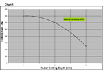
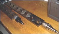
CAT 40, BT 40, HSK 63A and BT 40 FF (face and flange contact) with a moving flange were tested and achieved 1.3 hours of tool life on the CAT 40, 1.6 hours of tool life on BT (attributed to the shorter projection of BT vs CAT), 2.0 hours with the HSK and 3.6 hours with the BT40 FF. (See Figures 1 and 2).
Coating Technology, Geometries and Accuracies
Another area of advancement is in coating technology, geometries and accuracies offered by end mill manufacturers today. One particular area of advancement is providing geometry as standard to replace jig grinding with hard milling. The use of this process will reduce your machining time in half and increase the part quality.
Importance of the Right Machine, Software, Cutters, Toolholders and Training
Before we examine the cutting tool, let’s make sure the machine, software and toolholders are all in place.
Machine, Software and Toolholders
First you need to evaluate the machining center of choice. This first test is a ball bar test that shows how accurate the machine can make a circle. Your local machine dealer or service center should be able to test the machine.
After testing the machine, some parameters on the controller can be adjusted to increase the quality of the circle. In some instances, there may be a mechanical problem or one with the controller settings.
Second is the programming of the part. A helical style toolpath will be required to hard mill these bores. The code for this operation will have an X, Y, Z, I or J on the same line. You will need to turn on helical interpolation on the control. If you are using programming software, a 3-D model of the area to be machined needs to be developed. The diameters, depth and locations of the holes will be precisely developed according to the part print.
Another method for developing the code needed for this process is by the use of Macro B programming, which gives the machine operator the ability to make all the adjustments to a simple program in the controller to make any size hole at any location, for any depth without a 3-D model. You will need to turn this option on in the controller.
The third step now that you have checked the machine and programmed the part, is choosing the toolholder and end mills. The toolholder needs to keep the cutter TIR to less than .0004” for tool life and quality surface. Usually a high quality milling chuck or shallow tapered collet chuck will provide this run out. Heat shrink is another option.
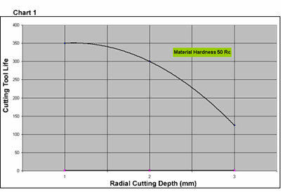
The final step, but also equally important is the correct end mill. A multifluted end mill with a maximum run out of .005 mm is recommended. In addition, the tool should have very short flutes to reduce the area of contact as you are extending into the machined bore (see Figure 3).
Machining Components Unattended Or Lights Out Machining
Lights out machining is a way to add machine time to your shop. It also will help you keep your mold and die tolerances from being polished out. If you have parts that take hours to run in the machine or you have parts that spend days in the polishing department, you are a candidate for lights out machining
Reasons Shops Have Not Taken the Plunge
Many shops have reasons or excuses for not machining lights out. Following are three of those excuses.
- “Our tools do not have the ability to run for eight hours, I have to use three tools to finish one part.”
This is a myth, machine tools, toolholders and cutters today have the capability of running lights out. - “We purchased these expensive end mills and when I start machining, I am cutting on zero and by the time we finish cutting it’s cutting at a positive .001.”
Your spindle heating up and not accounting for this in the program could cause this problem. - “I cannot seem to get the finishes required to eliminate polishing.”
A factor affecting this may be the software used and the ability to create code that is fine enough to finish a part.
Steps to Implementing a Lights Out Strategy
To begin, you need to evaluate each of these reasons and then determine possible solutions to help achieve lights out machining.
1. “Our tools do not have the ability to run for eight hours …”
First you should check the toolholders being used. Look at the tapers and if you see excessive wear on the holder, then you’ll know the spindle needs to be reground. If the spindle seems fine, check the quality of toolholder used. High quality milling chucks for roughing and flat taper collet chucks or shrink fit for finishing are ideal.
If both of these are fine, then check the milling cutter. Many times, the customer purchased the best priced product, rather than the correct end mill for the material, hardness and application. If all of the above items are correct, the milling cutters will be capable of running for the required cycle time.
2. “We purchased these expensive end mills and when I start machining, I am cutting on zero and by the time …”
As a machine is warming up, you will see the tip (end) of the tool move either positive or negative Z because of the heat changing the steel taper of the spindle and the holder. If the spindle type is a CAT or BT style without face contact, you will see the cutting toolholder sucked up into the spindle. If you are using a taper style with face contact, you will see the cutting toolholder pushed out of the spindle because of the spindle nose growing down. This growth will cause either positive or negative growth on your part.
You can check to see the growth of your machine by doing this easy test. If you have a tool probe in your machine you can create a program that will run the spindle for five minutes and then check the tool length. Run for another five and then again check the tool length. Do this for an hour and chart out your results. You will start seeing a pattern emerging, showing you how long it takes your machine to stabilize the Z growth. Once the machine gets to this point, the spindle chiller will keep it within a range that should be suitable for machining for long periods of time. You also will lose stabilization if you change the spindle speed or tool change. Now you will have to re-stabilize the tool for this new variable change. Once you know your machine, you can build this pattern into your programming.
3. “I cannot seem to get the finishes required to eliminate …”
The next part of this is the ability create code fine enough to avoid polishing. You can accomplish this with special software made just for this process. It will put toolpath evenly across the entire part with out having high spots that will need to be buffed out.
The other features you want to look for in the software you choose are as follows:
- High Efficiency Roughing: This feature has the ability to perform techniques like corner profiling and trochoidal. If you are cutting mold and die materials then these features are a must for extending tool life. When slot milling to trochoidal milling was tested the results were outstanding. Trochoidal gave 9X the tool life over slotting.
- Z Level Finishing: This feature can be used for geometries that have surfaces at angles greater than 30 degrees. With the option of offset turned on in the software you have the ability to complete your part program in a short amount of time.
- Surface Finishing: This is used when you have surface angles under 30 degrees. This is the technique that the shop owners like the most. This will give a swiped look to your parts.
- Re-Machining: This feature in the software details the part by removing the last radius used. This is where you put the detail into the part by using micro diameter end mil
When looking at software for mold and die you should have the company come to your shop and show you how they would program your parts. A good software company will be able to send a technician who can machine and program to today’s technology. If they don’t have a specialist for your process then you should look for one that has technical support for your type of parts.
For example, you should look for software that is not developed for general machining, but one that has the needed techniques for mold and die machining already built in. Testing of programming software developed for general machining against one specifically developed for mold and die machining showed a huge difference. The general machining software program took 2.5 hours to program the part and the process that needed to be created for that software was four pages of picks that the operator had to go through just to get what he wanted. The mold and die machining software took 15 minutes to create the part and a quarter-page for the process.
Achieving Maximum Productivity
This article has examined two of the five principles for improving your shop’s maximum productivity: (1) why and how to move your component finishing to hard milling and (2) why and how to implement lights out machining, and it also briefly touched upon replacing EDM with hard milling. None of these processes can be accomplished overnight, but with a strategy and plan these steps can help you reduce your manufacturing costs and compete with overseas suppliers. The part of this series in the next issue will focus on knowing the difference between high-speed machining, conventional machining and hard milling, and discuss a strategy for determining when to hard mill a part complete and when to high speed machine prior to hard milling.
Related Content
Mold Builder Meets Increased Domestic Demand With Automated Cells
Burteck LLC experienced significant demand increases due to reshoring and invested in automated machining cells to step up its production output quickly and avoid losing business.
Read MoreMMT Chats: Eliminating the Noise to Stay Focused on the Customer
Metro Mold & Design joins me to discuss the value of the 80/20 rule as a business strategy, its talented cross-functional team, the role of automation in mold building and molding, and the continuing impact of COVID-19.
Read MoreDynamic Tool Corporation – Creating the Team to Move Moldmaking Into the Future
For 40+ years, Dynamic Tool Corp. has offered precision tooling, emphasizing education, mentoring and innovation. The company is committed to excellence, integrity, safety and customer service, as well as inspiring growth and quality in manufacturing.
Read MoreOvercoming Barriers to Automation Integration in Precision Moldmaking
It’s easy to imagine the advantages automation offers the moldmaking process, but it's challenging to change one’s mindset, develop a plan and invest.
Read MoreRead Next
Part Three of a Three-Part Series Five Steps for Improving Your Shop’s Maximum Productivity
An explanation of the differences between high-speed machining and conventional machining; and, general thoughts on when to high speed machine and heat treat versus hard milling.
Read MorePart One of a Three-Part Series Five Steps for Improving Your Shop’s Maximum Productivity
Learn how to evaluate your shop’s productivity and begin increasing it by considering the variables of implementing hard milling and high-speed machining.
Read MoreHow to Use Continuing Education to Remain Competitive in Moldmaking
Continued training helps moldmakers make tooling decisions and properly use the latest cutting tool to efficiently machine high-quality molds.
Read More
