Cleaning a Flashed Hot Manifold, Part Two
The steps of a typical clean and rebuild of an encapsulated system.
Editors note: This is part two of a three-part series. You can find the links to the entire series below.
Part 1: A look at in-house and outsourced cleaning
Part 2: Steps of a typical clean and rebuild of an encapsulated system
Part 3: Cleaning nozzles, manifolds, electrical boxes, assembly & final check
Last month we discussed the pros and cons of sending a flashed manifold out for repair versus performing this task in-house. This article will begin to deal with the disassembly, troubleshooting, cleaning and reassembling of a typical, and flashed 16-cavity valve gate manifold.
Obviously there are many different makes of hot runner manifolds currently being used in the making of plastic parts today. Relevant (and most critical) design differences that will affect a manifold’s potential to leak concerns how the nozzles, sprue and any cross-overs (or bridges) are connected to the manifolds. These components are either bolted to, threaded into or rely on a compression stack, and sometimes a combination of all three. Each type has its trade-offs concerning required maintenance of the system and the overall ease of installing replacement parts, such as thermocouples, nozzles, nozzle tips and heaters.
Regardless of flowery forecasts made by manifold sales folks, the ease at which a manifold system can be maintained will not be apparent until the system has some hours on it (a million cycles would be nice), giving internal components, pockets and tooling clearances time to collect vent residue (greasy film or powders) and weepage (gooey, degraded plastic).
Also impacting manifold condition are molds stressed through weekend shut-downs and hurried Monday morning start-ups along with touchy gate/valve pin tip configurations that promote out-of-spec gate vestiges—forcing processors to fiddle with the parameters.
Some systems require a complete teardown just to replace a nozzle heater or thermocouple. On others, if specific components are disturbed or removed they too must be completely disassembled and cleaned before reassembly to ensure proper component stack dimensions.
The level of disassembly/reassembly (labor hours and skill level) required over time to replace basic components along with the usage (cost) of the components will determine the true ease of maintenance with the system.
But obviously, any manifold that encapsulates easily (easily meaning that if a strict start-up procedure is not followed to the letter, the system has the capability to blow at multiple locations) will not be a popular choice among those of us who have to fix or run them.
For the sake of fairness and consistency, we will examine areas of concern regardless of the manifold make and model.
Structured Maintenance
In manifold maintenance, the same five basic principles that apply to a mold also apply to an encapsulated manifold. The only difference is that troubleshooting the source of the leak could be ongoing throughout the repair process as plastic is removed and more tooling is exposed—allowing better visual inspection of seal areas and components, right up through assembly of the cleaned components.
Here is an overview of the five basic steps that will occur on an encapsulated system:
1. Disassemble
- Remove the valve pins and clamp plate, and disassemble mold to gain visual access to the back of manifold.
- Pay attention to tooling clues that can point to the leak source (bent, broken or galled valve pins and the amount and type of residue around the pin).
- Remove enough plastic as to facilitate separating the manifold and electrical box from the plate, so that you can clean these components separately.
2. Clean
- Clean clamp plate, manifold plate channels, counter-bores and valve pins (ultrasonic).
- Clean nozzles, heater and thermocouple wires and manifold (by hand).
3. Troubleshoot
- Inspect seal areas of components for obvious cracks and plates for hobbing and bolts for looseness.
4. Assemble
- Reassemble to stage one.
- Electrical check.
- Final reassembly to stage two.
5. Final Check
- Electrical check ramping heaters up to processing temp with water flowing through appropriate channels.
First Signs
Let’s begin with the mold in the press. The first noticeable sign of a flashed manifold is usually when smoke is seen rising from the top of the stationary side, or plastic oozing from places it shouldn’t … then the panic and finger pointing ensues.
But there are other, more subtle clues that might point to a manifold leak, such as molds that produce periodic incomplete shots, shorted out heaters and thermocouples in a particular quadrant.
Paying attention to these signs can alert a processor to a possible manifold malfunction and allow them to shut a mold down before the manifold is totally encapsulated.
If In Doubt, Check It Out
If there is even the slightest suspicion that a manifold has flashed, the processor should put a few pellets of a red resin or contrasting colorant into the melt stream (in the nozzle tip), then shoot the mold two to four times before it’s pulled to aid in locating the source of the leak.
While pulling a mold suspected of a manifold leak would seem like a waste of production time to many, the eight to 10 hours it might take to do this could save several days if you catch the manifold in the initial stages (less than one-third full) of total encapsulation.
But it takes an experienced processor to notice these signs and request that the mold be pulled for a manifold inspection based solely on suspicion. Many will just let it go until it becomes obvious that the toolroom has a problem. We will assume as much and elaborate on the above five steps.
Disassembly
- On valve gate molds with valve stems accessible from the back of the clamp plate, it is possible to remove the valve stems cold with a small slap hammer, but this practice could cause the head of the stems to break off, so it is safer in most cases to warm up the nozzles and, if possible, the manifold to about 250 degrees to allow the pins to be removed with less impact.
- As with all tooling, make sure the valve stems are numbered (use a carbide cutter in a hand-held grinder), a home location preferably somewhere on the head or stem, and place them in a wooden or plastic base drilled with an appropriate number of marked holes to keep them upright and separated.
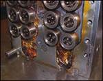
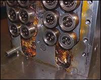
- Remove the backing plate (usually the “A” side clamp plate) to gain access to the backside of the manifold. Here you might see your first clue. Look for the path of the red resin. Manifold and nozzle seals that fail will allow the plastic to flow from that point outboard and follow the path of least resistance. The plastic will flow through wire channels in a laminar method, just as it does through a runner, so the resin around the initial point of failure will be more burned (degraded). This means the freshest looking flow front is usually furthest away from the source of the leak, and has been cooking the shortest amount of time.
- Notice the direction of the shot waves of resin that ripple away from the leak source paying particular attention to these flow fronts and the condition of the plastic. Is it burned (first place to leak) or fresh (last place to fill)?
- Before attacking the plastic with a ham-mer and chisel, look hard at the source
of the leak (here is where the red resin really helps) and try to confirm by examining the seal point in this area looking for a resin film between the tooling that would indicate separation. If an area looks promising, remove the plastic and check things out before continuing on. - A faulty seal between a nozzle and the manifold is easier to detect since the plastic rod formed at the junction should be smooth with no plastic washer attached to it.
At this point you will either discover the source/root cause of the leak, or you will find nothing and proceed on with more melting/chipping/cleaning.
Make good use of the heat gun (a Master Appliance Heat Gun #HG-751-B works great) and your brass chisel. The heat gun will soften much of the plastic in the channels to a point that you can more easily remove it from around the wiring, while carefully working your way down the channels.
If nothing is found during initial plastic removal, then remove enough plastic to separate the manifold/nozzle/electric box assembly from manifold plate. This will allow the plate to be cleaned in the ultrasonic while the nozzles and manifold are being inspected and cleaned by hand. Crank up the ultrasonic temperature to 200 degrees and tilt the plate forward in the tank, so the resin/weepage will liquefy and run out of the counter bores and channels.
While the plates clean in the tank, you can now remove the nozzles from the manifold, carefully, one at a time looking for signs of seal separation and feeling/watching for loose bolts. If gate tip edges are critical, wrap the tips in masking tape to protect them from accidental dings.
After all nozzles have been removed from the manifold, set them aside (still connected to the electrical box) and clean the manifold with a brass putty knife and ending with a fine/medium coarse Norton stone.
Next: Cleaning nozzles and manifolds, electrical boxes, assembly and final check
Related Content
Machine Hammer Peening Automates Mold Polishing
A polishing automation solution eliminates hand work, accelerates milling operations and controls surface geometries.
Read MoreMaintaining a Wire EDM Machine
To achieve the ultimate capability and level of productivity from your wire EDM on a consistent, repeatable and reliable basis, regular maintenance is a required task.
Read MoreIt Starts With the Part: A Plastic Part Checklist Ensures Good Mold Design
All successful mold build projects start with examining the part to be molded to ensure it is moldable and will meet the customers' production objectives.
Read MoreTreatment and Disposal of Used Metalworking Fluids
With greater emphasis on fluid longevity and fluid recycling, it is important to remember that water-based metalworking fluids are “consumable” and have a finite life.
Read MoreRead Next
Cleaning a Flashed Hot Manifold, Part Three
Cleaning nozzles and manifolds, electrical boxes, assembly and final check.
Read MoreCleaning a Flashed Hot Manifold, Part One
A look at in-house and outsourced cleaning.
Read MoreAre You a Moldmaker Considering 3D Printing? Consider the 3D Printing Workshop at NPE2024
Presentations will cover 3D printing for mold tooling, material innovation, product development, bridge production and full-scale, high-volume additive manufacturing.
Read More
