Moving High-Technology Machining into the Mainstream: Part II
Positional and continuous five-axis machining is an essential step in achieving correct ROI and improving delivery times.
In last month's article "Moving High-Technology Machining into the Mainstream: Part I" (May 2004), the benefits of high-speed machining (HSM) were outlined as well as the strategies that are needed to gain benefits. In this article, the options for five-axis machining will be discussed along with some tips on the ways to ensure that your investment provides the expected returns.
Positional Five-Axis Machining
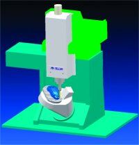
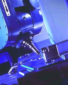
In five-axis machining, there are two distinct types of machines. First, there are those machines that are smaller versions of the equipment used for many years by the large companies, with all five axes of movement being generated through changing the orientation of the head. The more popular option with smaller components is to have a fixed orientation for the head, with the extra two axes being produced by tilting and/or rotating the bed holding the workpiece.
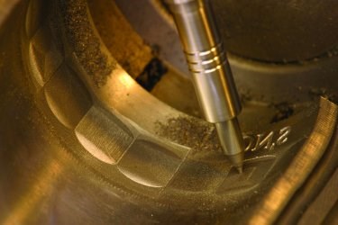
There has been considerable use of continuous five-axis machining, in which the relationship between the cutting tool and the surface being cut is constantly changing in all five axes. In contrast, the most commonly used type of five-axis machining in the moldmaking industry is positional five-axis machining. This technique, also known as three-plus-two machining, has the head oriented into a series of positions and the machining carried out as a set of discrete operations. With both positional and continuous five-axis machining, shorter cutters can be used since the head can be lowered toward the job and the cutter oriented toward the surface. As a result of the shorter length, there is less vibration in the cutter so higher cutting speeds can be achieved with no loss in accuracy.
A second major benefit is the ability to machine complex shapes in a single setup. This saves time when compared to performing the job in a series of setups, and also reduces the time and cost of making fixtures. Furthermore, with multiple setups, there is always a possibility of incorrect alignment each time the part is moved.
Another area where five-axis machining can give huge timesavings is hole drilling. While this may seem trivial in comparison to the complexity of machining a complex core or cavity, drilling a series of holes with different compound angles is extremely time consuming. If a three-axis machine is used, a different setup must be used for each hole. In addition to the extra time required, it is very easy to make a mistake when changing between a long series of complicated setups. With a five-axis machine, the head simply has to be oriented along the correct axis and the drilling can be completed much more quickly.
There are several factors that have made positional five-axis machining the preferred approach. One of the main reasons is that machining can usually be undertaken more quickly. Once the correct orientation has been achieved, the fact that the head is then fixed means it is possible to operate at high spindle speeds. With continuous movement of the head, it is difficult to operate at higher speeds because of the inertia that has to be overcome. In addition, once the new workplane has been set, it is easy to check for possible collisions or gouging. These calculations are much more difficult with continuous five-axis machining.
Continuous Five-Axis Machining
With continuous five-axis machining, there can be simultaneous movement in all five axes. The main challenge for companies using this approach is to ensure that the head does not collide with the job as the orientation is changing. This is less difficult when machining a core but can be much more problematic when machining inside a small but complex cavity. Similarly, for component manufacturers, there can be major challenges when machining fine details of the internal ports of an engine or between the blades of a small turbine.
One of the most common techniques for continuous five-axis machining is keeping the cutter approximately normal to the surface being machined. This approach has benefits when machining structures in the aerospace industry. Indeed, it is essential when machining flat surfaces, such as those at the bottom of a pocket. However, it is less appropriate for other components, where access to the surface being cut will be more difficult. It also can cause problems in moldmaking, since the parts being machined, and the individual details within them, are typically much smaller.
Machining normal to the surface will require the machine head to travel a greater distance than necessary when machining a convex surface and will increase machining times. It may be found that the normal position is inaccessible by the machine head, while, in other cases, it will be impossible to maintain the 90-degree angle without a collision with another section of the model.
Maintaining the cutter at a 90-degree angle to the surface of the part means that only a small part of the cutting surface of the tool is ever used. As a result, tool life is much shorter. Also, the tool tip travels a shorter distance at a given rotational speed than the full width of the cutter, so the material removal rate will be lower when using ball-nose cutters.
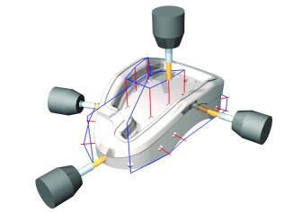
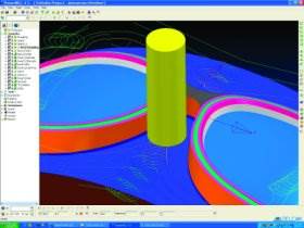
An alternative approach is to generate five-axis toolpaths based on machining through a point or to a point, to or from a line, or from a simplified surface. Some software incorporates automatic adjustment of tilt angles for both lead and lag (lead is measured in the cutting direction; lag at right angles to the cutting direction). Control of both lead and lag can give better cutting conditions, while the lean angle is used to avoid collisions. The software will also calculate gouge-free leads and links as the machine tool moves between the various surfaces within a part. These ensure that gouges are prevented and that collisions do not occur between the cutter and the part being machined.
Much work has been undertaken to make programming easier for five-axis machining. For example, secondary axis limiting has been added to ensure that the program generated will not attempt to move outside any limits in the machine tool's range of movement. Contact point analysis allows the user to ensure that only the cutting surface touches the component and that rubbing with the shank is avoided, and contact point feedrate control enables the feedrate to be set based on the cutting speed rather than the rotation rate of the tool tip. This last enhancement is very important when cutting some of the more difficult materials.
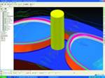
In addition, simulation programs allow users to see on the computer exactly what will happen on the machine and eliminate problems on the shop floor. The simulations will indicate any areas where the machine tool is attempting to move outside its operating parameters and also any movements where collisions could occur. Correcting any programming errors on the computer is, of course, much cheaper than finding the mistake on the machine tool.
The use of these simulations can also help ensure that maximum productivity is obtained from the machine tool. For example, the user can assess the effects of placing the component in different positions on the machine tool bed or can evaluate different fixtures to see which orientation of the part gives the most efficient cutting conditions.
CAM Isn't Everything
Further development of strategies to support the latest machining developments will continue, as will the efforts to make programming easier for both the moldmaker and production engineer. However, no matter how good the CAM system may be, it is essential that all parts of a company's machining operations are reviewed when making the transition to these new types of machining. Many of the unsuccessful installations that have discouraged investment in these new technologies have hit problems not because of a failure in the machine tool, but because other factors contributing to efficient operation have been ignored.
Buying the latest machine tool will give little benefit unless it is fitted with a modern control system. Similarly, using slower CAM software or a less powerful computer will lead to frustrating delays, with the new machine tool lying idle while NC programs are being generated. Finally, suitable cutters must be used or one will lose any gain in machining efficiency in the increased downtime needed to replace broken or damaged tooling. To achieve the correct ROI and to give the expected improvement in delivery times, a balanced investment in each aspect of the process is required.
Investing in the Future
Smaller companies must invest in new technology if they are to remain competitive and give guidelines on the application of the new techniques. Changing established ways of working will always be a challenge, but it is one that must be faced to ensure the survival of many manufacturing businesses. The alternative is to see work going to countries that can cheaply undertake simpler and routine manufacturing operations because of cheaper labor. Others can undertake complex work more efficiently and more accurately by using the latest technology.
At the moment, there is still a gap between these two extremes where business can be found. However, that gap is constantly reducing. Cutting wages is not a realistic option to increase competitiveness, so increasing productivity is the only practical way to remain able to offer the quality and delivery times now demanded at a price customers are prepared to pay.
Related Content
How to Analyze and Optimize Cutting Conditions to Reduce Cycle Time
Plastic injection mold design and manufacturing company puts NC program optimization software module to the test. The results were surprising.
Read MoreHow to Manage Wall Thickness Changes in Your Mold Design
To ensure even filling and cooling, consider wall section transitions, corners and fillets, ribs and bosses, lip and rim designs and CAE flow simulation software.
Read MoreThree Good Reasons to Switch from Three- to Five-Axis Machining in Moldmaking
Five-axis machining technology is a great tool in the moldmaker toolbox.
Read MoreWhat is Scientific Maintenance? Part 2
Part two of this three-part series explains specific data that toolrooms must collect, analyze and use to truly advance to a scientific maintenance culture where you can measure real data and drive decisions.
Read MoreRead Next
Moving High-Technology Machining into the Mainstream: Part I
To achieve the maximum ROI, companies must consider the machining strategies they apply and the supporting software, hardware and cutting tools used.
Read MoreHow to Use Continuing Education to Remain Competitive in Moldmaking
Continued training helps moldmakers make tooling decisions and properly use the latest cutting tool to efficiently machine high-quality molds.
Read MoreReasons to Use Fiber Lasers for Mold Cleaning
Fiber lasers offer a simplicity, speed, control and portability, minimizing mold cleaning risks.
Read More
