Mold Simulation and the Right Molding Press Solve High-Tech Device Design/Fill Challenges
Icon Injection Molding Inc. is never one to back down from a challenge. So when the company’s long-term customer Taser International approached Icon with its newest project, the Taser XREP® (Extended Range Electronic Projectile) Cartridge, Icon’s engineering team began looking at ways to design and manufacture this unique and challenging device.
Share
Read Next
Icon Injection Molding Inc. (Phoenix, AZ)—a moldmaker/molder specializing in complicated mold packages primarily in the law enforcement, safety and security industries—is never one to back down from a challenge. So when the company’s long-term customer Taser International—best known for its Electronic Control Devices (ECDs) for law enforcement/corrections personnel, professional security personnel, the military and consumers for personal protection—approached Icon with its newest project, the Taser XREP® (Extended Range Electronic Projectile) Cartridge, Icon’s engineering team began looking at ways to design and manufacture this unique and challenging device.
The Taser XREP Cartridge is literally a cartridge the size of a regular shotgun shell, loaded with the Taser components that shoot a wireless charge. “It packs twice as much power and has four times the range as the standard Taser guns do,” explains Icon President and Co-owner Danny Kleitsch.
The Taser XREP Cartridge is a self-contained, wireless electronic control device (ECD) that deploys from a standard 12-gauge pump-action shotgun. It is the most technologically advanced projectile ever deployed in this manner, and delivers a Neuro Muscular Incapacitation (NMI) bio-effect similar to Taser’s other well-known devices such as the handheld Taser X26™ ECD.
The Taser XREP Cartridge however, can be delivered to a maximum effective range of 100 ft (30.48 meters), combining blunt force impact. The battery supply is fully integrated into the chassis and provides the power to drive the XREP projectile engine. In both the XREP series Cartridges, the nose assembly of the projectile contains forward facing barbed electrodes. On impact, the forward-facing barbed electrodes attach to the body of the target. The energy from the impact breaks a series of fracture pins that release the main chassis of the XREP projectile, which remains connected to the nose by a non-conductive tether.
The XREP projectile autonomously generates NMI for 20 continuous seconds. As the Chassis falls away, six “Cholla” electrodes automatically deploy to deliver the NMI effect of a greater body mass.
A Complex Project: Because of the size of the XREP Cartridge, and the number of components contained (23 injection molded parts), which are extremely small with very tight tolerances and packed closely together, Icon’s project management had the task of making sure all molds were designed and built to extremely precise tolerances. In many areas the tolerances were as held as closely .0001-0002 in steel. The XREP Flight Stabilizer Fins had to have very thin walls (.009-.011 wall thickness).
Kleitsch explains that Icon had more than 20 moldmaker, five designers and three molding experts from three different companies (Icon, domestic moldmaker CAD Tools) and Taiwanese moldmaker Trocha). “Collaboration on this project was done with many extensive design review meetings in person with all necessary personnel from all companies involved and followed through the mold building process with WebEx or Go To meeting on-line conferencing,” he states. “Up-front communications was a key to the success of this project as 95 percent of the problems were removed prior to cutting steel.”
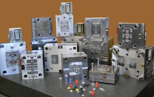
One of the molds Icon built for the XREP project was a six-cavity mold that required the company to purchase a high-speed Nissei injection molding press, an NEX15 with upgrades including a 19.7” per second injection velocity capacity with no accumulator. The press was fitted with automation for part removal so that the mold can achieve fast cycle times for high productivity. According to Kleitsch, Icon purchased this press just for this job. “Taser wanted to have an injection molded part that was 0.009 wall thickness and it was half an inch long,” he explains. “That is no problem when running viscous and really thin watery material, but the materials we had to run this part in had to be engineering plastics, which were much thicker and much more susceptible to thicker wall thicknesses. We didn’t want to degrade the plastic so we bought this press.
“Now, it is our number-one booked press for many different jobs because we can run so many small parts—little micromolded parts that this press is ideal for,” he elaborates. “It has a very fast injection rate and we have two barrels for it. It is probably 90 percent booked in our shop right now, and we didn’t even know we needed it until we bought it for that job.”
Mark Hanchett, mechanical engineer with Taser’s R&D department says that the very thin walls of the parts presented a challenge in material selection. “We had to deal with materials that normally don’t flow well through these thin walls, one example was to heat the material to maximum recommended temperatures,” Hanchett explains.
Icon and Taser worked closely with Icon’s material suppliers, and chose a Sabic Lexan EXL, an experimental grade of polycarbonate with very high impact modifier content for many of the parts. A custom LNP Teflon-filled polycarbonate was chosen for the XREP’s Flight Stabilizer Fins, with a material shot size of a mere .0276 grams each. The Shell base is a multi-component part, which includes EXL-polycarbonate molded over a metal injection molded (MIM) ring for improved mechanical properties when fired and ejected.
The fact that many of the 56 total mechanical components that comprise the XREP are technically micro-molded parts, the intricate detail of the parts presented the biggest challenges. “There is one molded component that mates with 15 other components, but that component is the size of a dime,” says Hanchett. “And all of these components must be contained in a product that is the size of a standard 12-gauge shotgun shell.
“First, Icon built all single-cavity prototype molds to proof out Taser’s mechanical designs,” Hanchett continues. “After months of testing multiple materials and many engineering changes with the prototype molds, we were ready for the production tooling. At that time, Icon’s design team worked closely with all other involved design teams to produce quality, efficient running molds. SolidWorks was used for all CAD modeling and mold designs. Then, all molds were pre-flow tested at Icon with a mold simulation program. Icon researched the materials and performed Simpoe-Mold® plastic injection simulation analysis on part designs and hot runner manifolds to ensure consistent quality.”
The Simpoe program simulates the complete manufacturing process of plastic injected parts—from filling to warpage—and performs functions like reading CAD data, meshing, solving and results processing, “It told us whether the part would run in the press we chose, did we choose proper materials and where we should vent,” Kleitsch says. “This analysis results in success on the shop floor.
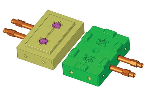
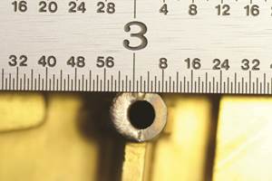
“We like this type of challenge,” Kleitsch continues. “Our design, engineering and molding teams sit and brainstorm about how we can get the molds to work properly in all situations—and to make the best quality part and still bring down the costs for our customers. We want to be leaders in this area. And with the right tools—like the Nissei molding machines, special surface coatings to make the materials flow a little bit better, opening up an area of the gate, or changing the pin diameter to an hourglass shape instead of a round pin shape. All of these tools make the difference in the failure or success of any project.
“Again, this is where Simpoe was extremely helpful,” Kleitsch adds. “Every time we did an analysis, we saw how the part flowed and where the pressure drops were. We had to put custom venting in certain areas so we could get the gas out and get the material flowing. We learned the best place to gate it. Once we went to the production tools, we had ironed out all of the problems with designs and our molding processes.
Icon went through a number of mold revisions to get the product to work, Kleitsch notes. “We were trying different gating locations, thicknesses. We had to bump up the thickness and we had a material that worked really well, but would still not fill at.009 wall thickness so we bumped it up to .011 in some areas of the part. By adding a variable thickness this took care of all filling problems and also worked with Taser’s manufacturing process
In all, Icon completely managed and co-designed and co-manufactured 18 prototype tools and 20 production tools for the manufacture of the Taser XREP Cartridge, all of which make the extremely complex parts that comprise the XREP Cartridge. Taser’s management is extremely happy with Icon’s capabilities as a supplier. “Taser International’s Design and Development Team has partnered with Icon Injection Molding on most of our most critical and ground-breaking projects since 1997,” says Milan Cerovic, Mechanical Engineering Manager. “We recognized that Icon shares the same core values as Taser International does, along with innovation, technical expertise, competence and above all, quality and reliability. Their work ethic and leadership in their field are reassuring and motivating for us to work together in the future as we have been in the past.”
Related Content
Laser Welding Versus Micro Welding
The latest battle in finely detailed restoration/repair of mold materials.
Read More5 Hot Runner Tips for Moldmakers and Molders
Best practices for initial hot runner tryouts and effective preventive maintenance.
Read MoreMachine Hammer Peening Automates Mold Polishing
A polishing automation solution eliminates hand work, accelerates milling operations and controls surface geometries.
Read MoreHands-on Workshop Teaches Mold Maintenance Process
Intensive workshop teaches the process of mold maintenance to help put an end to the firefighting culture of many toolrooms.
Read MoreRead Next
Tips and Techniques: Mold Filling Analysis Now You Can Adapt Injection Mold Filling Simulation for MuCell
While mold-filling simulation is a very common tool for predicting the fill patterns of an injection mold, in our judgment there is not yet a commercially available, satisfactory filling simulation for microcellular foam molding.
Read MoreHow to Use Continuing Education to Remain Competitive in Moldmaking
Continued training helps moldmakers make tooling decisions and properly use the latest cutting tool to efficiently machine high-quality molds.
Read MoreAre You a Moldmaker Considering 3D Printing? Consider the 3D Printing Workshop at NPE2024
Presentations will cover 3D printing for mold tooling, material innovation, product development, bridge production and full-scale, high-volume additive manufacturing.
Read More
