Metrology Molds a Better Bottom Line
Improved accuracy saves time and drives down costs in the moldmaking process.
Share
Read Next
The moldmaking industry is often at the cutting edge of metalworking technology. Innovations in machine tool design, cutting tools and CNC programming are typically championed by moldmakers in their quest for increasingly precise tools. Highly accurate measurement tools are also becoming necessary for mold design and manufacturing, though the industry has been slower to adopt them.
The expanding use of CAD to design products and drive manufacturing processes has solidified the need for metrology to play a larger role in the moldmaking process. Historically, product designs were conveyed with a series of lines, circles and other geometric entities. With the advent of CAD, designs morphed into three-dimensional shapes primarily composed of surfaces. A car body is a good example. Years ago, automobiles were very boxy, but as technology advanced, their profiles became sleeker and more aerodynamic. Conventional measuring techniques using calipers, micrometers and height gages could handle lines, circles and radii, but struggled with freeform shapes that needed to be compared to the original 3D CAD model.
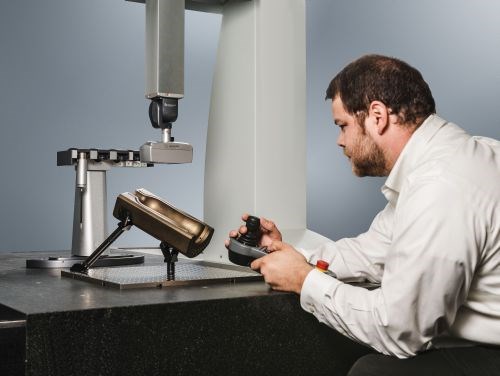
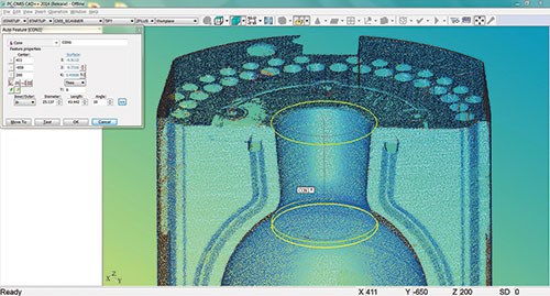
Metrology software is designed to verify freeform shapes with CAD-to-model comparison functionality found in sophisticated inspection solutions. Metrology hardware, such as a coordinate measuring machine (CMM), enables such CAD-to-model comparison by measuring a point on a part’s surface and relating it to its nominal value. Manual measuring gages are not able to handle such tasks to the level of precision required by the increasingly tighter tolerances across the industry.
The need for tighter tolerances on finished parts necessitates the move to higher-precision molds. This is due to the simple concept of compounded error. Any part, including a mold, will not be 100-percent perfect. It will include some slight error. Equally true, the material that fills the mold will also contain a slight error. If a machining process is to be performed on the finished mold, that step will introduce error as well. As error is added from each of these sources, it is compounded. If too much of the error is contained within the mold itself, it will have “used up” the allowable tolerance without factoring in error of the material and any machining process.
For example, if the allowable tolerance of a finished part is ±1 mm, and the mold meets specification to within ±1 mm, there is no room for error down the line. Typically, the mold should be accurate to approximately 10 percent of the final product’s value. So, in the given example, the mold should be accurate to within ±0.1 mm, providing the manufacturer a sliver of room for error for the tool and allowing the remaining processes to take up the rest.
Time Saved
Moving to an automated inspection solution saves time, which translates into saving money. To illustrate this point, consider the inspection of a motorcycle gearbox housing component. It would take more than a week to validate the component on a CMM using a touch-trigger probe. At the end of the process, if errors were found on the part, an adjustment would be made on the tool. After a few iterations, the component would eventually meet specifications. This process can be dramatically expedited after installing a laser scanner on the CMM. The same component could be scanned and the results achieved within approximately three hours.
Another example of time savings comes with the ability to reverse engineer tooling and warehouse the data electronically. Consider an automotive door panel built by an OEM. This panel is pressed into a shape that should line up perfectly with the CAD model. However, during this pressing, the panel
gives a certain amount of spring-back that results in a slightly different shape. The solution is to adjust the tool so the spring-back is accounted for in the finished product. The metal is overbent in the pressing process and springs back to conform
to its CAD nominal.
When the tool fails, the process is repeated. Precious time and resources are wasted to make the “perfect” tool, mount and press the part, analyze the spring–back, and remake the tool. By adding laser scanning technology mounted to a portable CMM, 3D data can be collected for surface modifications and uploaded to the master model. The master model then can be used to manufacture the tool.
Reduced Material and Tooling Costs
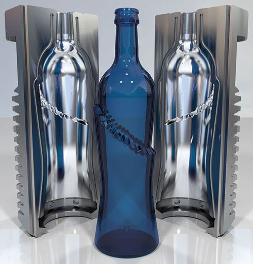
Another benefit in producing highly accurate molds is reduced overall material costs. In certain industries, a micron knocked off the thickness of a container’s side equates to a million dollars per year in savings for that plant. Controlling the amount of material used to produce a part is becoming an art form in the moldmaking industry. Moldmakers are continually searching for the difference between a “thin” container and a “too-thin” container. Using advanced metrology tools helps to find that boundary.
Tooling costs also drop as advanced metrology equipment comes into play. Multi-cavity molds can be engineered so each cavity is identical and mates perfectly with its counterpart. If one tool cracks, both tools do not become scrap. A new top or bottom can be easily reproduced and fitted to the remaining tool.
Zero Failure Rates
CMM technology can also be an asset to moldmakers during the design process. Certain products need to be designed to tighter tolerances due to their potential liability. For instance, a part that serves as an enclosure for liquids will need to meet strict tolerances so the enclosure does not fail and the liquid does not escape. A 5-gallon bucket, though a relatively simple part, may be used to hold bleach or paint that could do serious damage if it leaks. Finding the point where the product is secure, without investing resources and material in an over-engineered design, is a perfect application of metrology.
Metrology is the Key
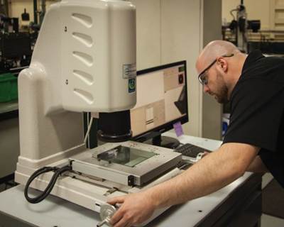
When traditional hand measurement tools such as calipers and micrometers are used to inspect a part’s features, the validity of the results is highly dependent on the operator’s skill level. Measurement inaccuracies due to operator error are virtually eliminated with today’s advanced metrology equipment, such as CMMs (including portable-arm CMMs), stereovision and laser scanners. With this technology, inspections can occur in a fraction of the time compared with manual methods. These tools also provide the accuracy required to meet tight tolerances needed to control material and tooling costs, as well as diminish product failure rates. Manual inspection methods may also restrict the inspection of complex 3D surfaces with hidden features.
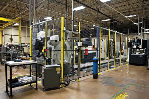
Metrology equipment can expand the automation potential for moldmakers. For example, an automated work cell can include a shopfloor CMM for electrode verification and workpiece positioning. Here inspection is the secondary function of the cell’s CMM. The process begins as a palletized workpiece or electrode is picked up by a robot from the machining center. After dirt and lubricant removal, the robot moves the part to the CMM for evaluation of the X, Y, Z and C (rotation in the X-Y plane) offsets, as well as necessary compensation for spark gaps. Adjustments are then made in the software, as the component is automatically delivered to a sinker EDM. When complete, the workpiece is returned to the CMM.
Big Rewards
While there will be growing pains, implementation of metrology technology promises big rewards for the moldmaking industry. As innovations in machining technology continue to enable greater precision and tighter tolerances, the industry must introduce necessary tools such as automated CMMs to ensure better results.
In the short-term, companies new to metrology technology will shoulder a learning curve and investment in capital equipment. The long-term benefits, however, will be cost savings that translate into rapid return on investment, as increased accuracy aids their manufacturing processes. These cost benefits are realized in the form of time saved, lower material and tooling costs, and a move to zero failure rates of finished goods.
Hexagon Metrology, Inc.
Related Content
Breaking Down 3D Scanning in Moldmaking
Identifying 3D scanning requirements and implementing the appropriate technology.
Read MoreVIDEO: Maintaining a Customer-Centric Culture
Progressive Components President Glenn Starkey talks about the importance of the customer and culture when developing technology solutions for the moldmaking industry.
Read MorePrecision Meets Innovation at IMTS 2024
After attending IMTS, it's clear that the integration of advanced technologies is ready to enhance precision, efficiency and automation in mold manufacturing processes. It’s a massive event, so here’s a glimpse of what the MMT team experienced firsthand.
Read MoreIndiana Mold Builder Decatur Mold Offers a History of Grit and a Future of Innovation
Decatur Mold Tool and Engineering Inc. serves as a tooling tour guide, helping busy tooling managers reduce uncertainty, lighten workload.
Read MoreRead Next
2014 Leadtime Leader Awards Winner: Westminster Tool Inc.—Bridging the Gap without Losing Focus
A strong sense of self and a focus on people enabled this mold manufacturer to rapidly expand pre- and post-manufacturing services without getting overwhelmed by its own growth.
Read More2014 Leadtime Leader Awards Honorable Mention: Aalbers Tool & Mold Inc
A rush of recent change for this moldmaker belies a long-term growth strategy that’s anything but aggressive. Key aspects of this cautious approach include strategic expansion, continuous improvement, extensive data tracking, and investments in workforce development and environmental sustainability.
Read MoreAre You a Moldmaker Considering 3D Printing? Consider the 3D Printing Workshop at NPE2024
Presentations will cover 3D printing for mold tooling, material innovation, product development, bridge production and full-scale, high-volume additive manufacturing.
Read More
