Meeting the Demands of Multi-Tasking: CAM and Machine Simulation
To fully realize the potential of multi-tasking machines, users must rely on CAM systems and machine simulators to keep pace with their advances.
It’s an all too familiar situation: intense competitive pressure, specifically from offshore manufacturers, is necessitating domestic manufacturers to improve their efficiency, productivity, quality and throughput in order to remain competitive. And in almost déjà vu fashion, domestic manufacturers are turning to advanced technologies to gain a competitive advantage. But today’s technologies come with their own demands and complexities making their adoption sometimes as challenging as the international competition itself.
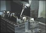
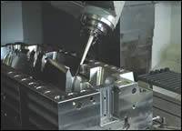
Multi-task machining (MTM) class machine tools—also sometimes referred to as multi-flow machine tools—are an excellent example of technology rising to meet the competitive challenge. MTM machine tools offer the user a unique system configuration, which allows the part to be accessed from all sides without having to be manually refixtured; the machine exchanges the part between spindles reorienting the part and allowing the tooling to cut in areas previously inaccessible. This machine-enabled repositioning eliminates the errors potentially introduced by manually repositioning and also eliminates the need for operator intervention. When a significant percentage of cost and quality is attributed to manual labor, MTM machines represent a very effective solution. Today, a growing number of parts are being produced entirely within one MTM machine.
So, whether you’re a mold shop using multi-tasking machine technology to eliminate mold build process bottlenecks, reduce work-in-process, decrease setup times, improve productivity, reduce time-to-market, create more shop capacity, achieve lean manufacturing or implement automation; or, you are just in the beginning stages of researching the benefits of MTM to your mold building operation, it is essential that you closely examine the programming capabilities that MTM offers.
The Programming Key
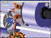
If it were only a simple matter of exchanging work-in-process stock from one spindle to another, MTM machine tools would be relatively straightforward to program. The programming software would only need to concern itself with the transfer commands and working with the part in the new orientation. But for MTM machine tool designers multiple spindles were just the starting point. MTM machine tools now provide the ability to cut with multiple tools not only at the same spindle at the same time, but also across multiple spindles.
CAM System Requirements
Having multiple tools cut at the same time significantly improves process efficiency, but it also significantly complicates programming. The first CAM programs developed dealt with conventional milling or turning machine tools. They programmed a single cutter cutting the material at one time. It was a single, sequential process, so fairly straightforward to handle. With the advent of multi-tasking, multiple tools can be cutting material at the same time. Tools can be cutting on the same part in the same spindle, or they can be working on separate parts in separate spindles. This gets even more complicated when dealing with more than two spindles and two tool groups. With multi-tasking what was previously a simple, sequential, single flow process all of a sudden becomes a complex, multi-flow program.
Process Coordination and Synchronization
In order to support multi-task programs, CAM systems must be able to maintain aspects of process coordination and synchronization that all need to be taken into careful consideration. Unlike a single flow program, an accurate time reference needs to be maintained. In addition to time, an accurate understanding of the machining context, such as feed and speeds, also needs to be maintained, particularly when two tools are being applied to the same part, such as a pinch turn operation.
In these situations, one tool will be considered the dominant tool and its cutting conditions control the speed of the spindle. The second tool’s cutting parameters are then determined by its position from the axis and the spindle speed. Ideally, the user should not have to concern himself with this level of detail; the CAM system keeps all of these details straight and provides the user with a simple to understand interface.
Machine Simulation
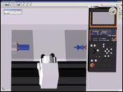
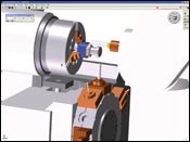
Because of the additional complexity of multi-task programs with their multiple tools cutting at the same time, multiple spindles, and parts being exchanged between multiple spindles, the need to accurately simulate and validate the programs before executing them on the machine tool becomes very important. Within machine simulation, there are a number of distinct phases: the machine tool model, virtual machine tool setup and the machine simulation/analysis.
For any machine simulation system, an accurate model of the machine tool needs to be used. These can either be developed by the user or obtained from an existing (commercial) library of machine tool models. The level of detail of the machine model greatly influences the analysis that can be performed with it. A minimal representation may allow a simulation model to be quickly developed, but it will also limit the extent the analysis can be performed. Alternatively, at some point, additional detail included in the model, such as the control panel display, knobs and switches, becomes more for appearance, than for any actual analysis benefit.
Once the machine tool model has been developed and prior to actually performing the machine simulation, the machine tool model needs to be set up in exactly the same way that the real machine tool on the shop floor would be setup. Tooling needs to be assembled in holders, assigned to and positioned in tool locations and offsets established. This initial process of setting up the machine tool model actually is extremely beneficial as it allows the user to establish and validate the machine tool setup as part of the overall machine tool simulation. Once completed, the settings validated through this virtual setup process can then be passed onto the operator on the shop floor for setting up of the actual machine tool. Proving out the machine setup offline can save valuable machine tool time on the shop floor.
Implementation Approaches
When it comes to machine simulation, there are three implementation approaches available, which offer different benefits to the user. Having a better understanding of these approaches will allow the user to best select which approach to use for their purposes. Since the different approaches are not usually exposed to the user, it may require some research by the user to determine which methodology is actually being used.
1. The most direct machine simulation approach is where the simulation functionality is integrated into the CAM application and runs directly off of the CAM system's internal representation. This approach allows the user to immediately analyze their process at any time while it is being developed without having to first generate machine code. This allows for quick review and incremental update cycles.
The trade-off for this quick turn-around though, is that the simulation is checking the process, not the quality of the CAM system’s G-code output. In general, with most of today’s post processors, once a post processor has been validated, G-code quality is usually not a problem. In addition, due to the complexity of most multi-task programs, there are advantages operating directly from the process model, such as having access to the entire process information. For example, any errors identified during the simulation can be traced back directly to the original operation for easy correction within the CAM system.
2. Rather than directly integrating with the CAM system’s internal process model, some machine simulations operate from APT CL output generated from the CAM system. APT CL is a generic G-code output that provides an intermediate exchange format for controllers. Though relatively portable, APT CL usually requires a subsequent round of post processing to format it for a specific machine tool/controller. By using APT CL, this approach avoids the expense of directly integrating into the CAM system’s internal process model. While APT CL does not offer the same level of information as the process model, basing the machine simulation off of APT CL does provide a level of output validation, since the APT CL data is output through the CAM system’s post processor.
The trade-off with this approach is that whenever the user wants to perform a machine simulation, the CAM system must first output an APT CL to feed it. Another interesting aspect of this approach is that APT CL currently does not have a standardized convention for multi-task programs. Because of this, special proprietary extensions must be introduced into the APT CL program to support multi-task constructs, like process flows, synchronization points and utility operations. Just as the CAM system’s post processor uses the extensions to flavor output for a specific APT CL post processor, it can also flavor APT CL output for a specific machine simulator based on its proprietary extensions.
3. The final machine simulation approach takes the APT CL approach even further by implementing a reverse post processor for the native G-code of specific machine tool/controller combinations. By directly supporting a machine tool’s native G-code, the machine simulator becomes an emulator for it. Of course, this approach is extremely expensive as it requires the simulator’s interface to handle all the machine tool’s subtle nuances of input. And when dealing with multi-task machine tools, the level of complexity that reverse posting entails can be daunting.
The trade-off from the user’s perspective: though this approach also requires the user to generate G-code output whenever a machine simulation is run, it can provide the most accurate validation of the G-code program output by the CAM system.
Summary
Multi-task machine tools have really just starting to come into their own in the manufacturing industry. We can expect that they will continue to play a major role in high-efficiency machining, while their configurations will continue to evolve into even more incredible devices. In order to fully realize their potential, users will rely on CAM systems and machine simulators to keep pace with their advances.
Related Content
Tolerancing in Mold Design, Part 1: Understanding the Issues of Conventional Bilateral Tolerancing
Mold designers must understand the location, orientation and form limitations of conventional tolerancing before changing to another dimensioning system.
Read MoreWhat Is Scientific Maintenance? Part 1
How to create a scientific maintenance plan based on a toolroom’s current data collection and usage.
Read MoreWhat is Scientific Maintenance? Part 2
Part two of this three-part series explains specific data that toolrooms must collect, analyze and use to truly advance to a scientific maintenance culture where you can measure real data and drive decisions.
Read MoreThree Good Reasons to Switch from Three- to Five-Axis Machining in Moldmaking
Five-axis machining technology is a great tool in the moldmaker toolbox.
Read MoreRead Next
Challenges to Five-Axis Machining for Moldmaking
When considering five-axis machining you must consider your goal for using five-axis machining on molds: to machine the complete part with the shortest cutters possible.
Read MoreHigh-Speed Machines Deliver Speed, Accuracy, Repeatability and Finish
The addition of high-speed machines that blend a reasonable cost with high performance helps one moldmaker realize a huge competitive advantage.
Read MoreReasons to Use Fiber Lasers for Mold Cleaning
Fiber lasers offer a simplicity, speed, control and portability, minimizing mold cleaning risks.
Read More
