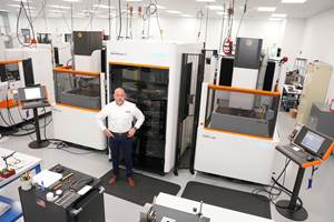
Investments in Productivity: Automation Integration In the Toolroom
By integrating machining, workpiece and cutting tool management, CMM verification, and a Web-based video and control system, a completely integrated cell producing fully qualified electrodes through automated manufacturing can be created.
Making significant investments in augmenting the manufacturing capabilities and capacities of its mold shop through the installation and integration of automated machining centers has enabled MGS to provide its customers an increase in productivity, a decrease in leadtimes and an improvement in consistency in delivering duplicate cores and cavities—creating a lights-out, time-to-market manufacturing environment.
The Manufacturing Cell
An example of the investments in productivity that MGS Mfg. Group made in the toolroom is demonstrated by the activities in the representative cell (see Figure 1)—built according to shop specifications and process requirements. Central to the integration of the cell is the unique CAD/CAM MRP integrated software—in effect creating an electrode printer.
This system eliminates human interaction with confirmed data, sending the specifications required to manufacture a qualified and measured electrode at the end of the process, much like the action of creating a document and instructing a computer to print to the selected device.
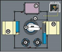
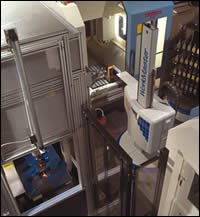
In this particular instance, the various stages of making graphite electrodes are accomplished using five different pieces of equipment. A three-axis, pick-and-place robot provides the means to access graphite blanks and cutting tools from the rotary magazines where they are staged. There are two high-speed CNC machining centers for cutting and a CMM, which is used to determine the accuracy of the cut. A Web-based vision system is incorporated to allow off-site monitoring and control if needed. The illustrated overhead view of the cell shows the relative placement of the components in Figure 2.
Sequence of Events
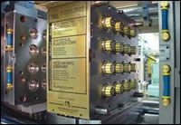
The level of productivity and quality attained by these manufacturing cells is demonstrated by following the entire sequence of machining a finished electrode from a blank piece of graphite. The integrated cell follows the schedule as written by the cell operators, which is based on mold delivery and internal requirements. For the purposes of this demonstration, a closure/cap will serve as the representative destination product (Figure 3). The tooling system designed to deliver the required volumes is a 16+16 cavity multishot rotational stack mold (Figure 4).
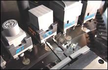
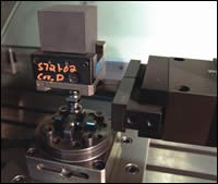
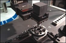
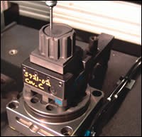
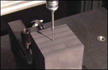
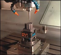
Prior to the start of manufacturing, the cell operator loads graphite blanks and verifies cutting tools as specified in the program. Pre-loaded/pre-qualified standard cutting tools remain resident in the rotary magazines—reducing or eliminating the downtime associated with the loading process. The CNC machine performs a self-check of every tool prior to the run and subsequently builds cutter specifications. After cutter verification, the robot turns and extends into the carousel (Figure 5), picking out the piece of material as per its work instructions, and places it into the CMM (Figure 6) to check Z height (Figure 7). The robot then moves the workpiece into the CNC machine (Figure 8). Positioning data is refined and stored to facilitate the accuracy of future cuts. The cutting tool is selected, cleaned with high-pressure air and examined via laser inspection. The resulting data is compared to the stored cutter specifications. Upon confirmation, actual machining will begin (Figure 9).
During all phases of roughing and finishing, the cutting tool is inspected and verified, ensuring the final accuracy and quality of the resulting electrode. If any significant wear is detected on the cutter, a new tool would be presented from a designated library of spare tools. It goes through the same verification process as the original and the machining continues.
After completion, the robot extracts the electrode and places it into its designated stage on the carousel, pending availability of the integrated CMM. When the CMM is ready, the robot takes the electrode from the carousel and places it into the CMM for inspection (Figure 10).
As a result of Web-based video and control systems, the function of the manufacturing cell can be monitored and manipulated at cell side, at the programmer’s desk or off-site via a secure portal on a Web site.
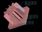
During the quality inspection stage, the resulting CMM data is overlaid with the original 3-D geometry using custom written software. Discrepancies in pre-determined critical dimensions are automatically identified and highlighted in various colors depending on measurements falling in graphite light or heavy range. An automatically generated tag is visible on all comparative points indicating the degree of discrepancy, if any (Figure 11). After evaluation, the toolmaker determines the required corrective action. This automated process results in several benefits with regard to complicated 3-D surfaces: it reduces or eliminates hours of CMM programming, tedious data entry of sequential sinker EDM operations and any potential for human error.
Other MGS tool manufacturing cells feature high-speed milling machines for hardened steel. Once again, a robot places and retrieves workpieces from a carousel. The cutters in this cell are continuously verified by laser and cleaned by highly pressurized air, as before. Upon completion, the robot removes the part, transports it to the carousel where it is stored for later use, and the robot continues with the next piece. This same automated technology is used in wire and sinker EDM cells.
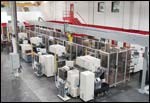
With regard to wire EDM cells, the newest automated installation features six integrated EDM centers, bookshelf staging areas and a CMM fed by a rail-mounted, six-axis robot. (Figure 12).
Summary
By integrating machining, workpiece and cutting tool management, CMM verification, and a Web-based video and control system, MGS has created an automated manufacturing environment, producing qualified electrodes and machined steel. MGS Mfg. Group currently has multiple automated machining centers at work in its tool shops—expediting mold construction, reducing the need for operator intervention, reducing leadtimes, improving quality and consistency over duplicated cores and cavities—for multiple tooling sets and/or spares, and increasing overall mold build capacity, all to better serve the customer.
Related Content
2024 Moldmaking Insights: A Year in Review Part 1
A look back at the top moldmaking trends of 2024, as revealed through MMT's analytics. This review highlights the most popular technical articles, case studies, tips and best practices that captured the industry's attention over the past year.
Read MoreDevelopments in High-Speed Machining Technology
There have been many exciting developments in high-speed machining relative to machining centers and controls, tooling and CAD/CAM systems.
Read MoreMMT Chats: Eliminating the Noise to Stay Focused on the Customer
Metro Mold & Design joins me to discuss the value of the 80/20 rule as a business strategy, its talented cross-functional team, the role of automation in mold building and molding, and the continuing impact of COVID-19.
Read MoreMold Builder Meets Increased Domestic Demand With Automated Cells
Burteck LLC experienced significant demand increases due to reshoring and invested in automated machining cells to step up its production output quickly and avoid losing business.
Read MoreRead Next
Reasons to Use Fiber Lasers for Mold Cleaning
Fiber lasers offer a simplicity, speed, control and portability, minimizing mold cleaning risks.
Read MoreAre You a Moldmaker Considering 3D Printing? Consider the 3D Printing Workshop at NPE2024
Presentations will cover 3D printing for mold tooling, material innovation, product development, bridge production and full-scale, high-volume additive manufacturing.
Read More


