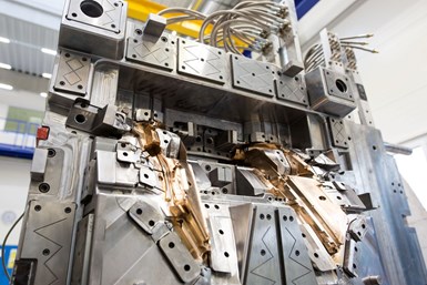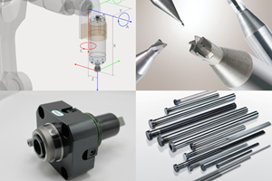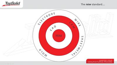
Mold designers can concentrate on more important tasks if your CAD/CAM software captures your mold manufacturing process. Photo Credit, all images: Top Solid USA
Every company is based on a foundation of knowledge. That knowledge is often taught from a senior mold builder to a junior mold builder. Sadly, that knowledge can be lost over time. Here we’ll focus on taking a real-world look at capturing and reusing company know-how. By using software automation, mold builders can instill company standards and best practices while speeding up the mold manufacturing process from design to production.
Mold Design Causes Challenges
Every business is based on a foundation of knowledge and the belief that the team can deliver a better product than the competition. So, let’s discuss that knowledge. Knowledge makes everything possible. Without it, we can’t grow our businesses. Knowledge is the foundation of any process, including the pricing system you use, the suppliers with whom you choose to work or the method you determine is best for manufacturing a mold. Everything comes from the knowledge your team has built over time.
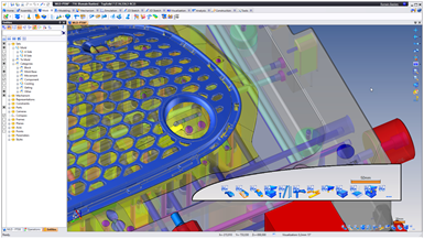
A bar is available to optimize the organization of the parts of the tooling, providing quick access and visualization.
For example, you land a new mold project. Then you begin with a preliminary design followed by a review with the customer, which often results in revisions. This step can take a while until each party agrees on the final design. You then deliver the design to your internal team or a contract manufacturer to complete the mold build. However, a lot happens between initial design and mold completion — from ordering materials and consumables to finish machining and assembly, mistakes can occur anywhere along that line. Here is where automation comes into play.
Every mold builder wants to stop simple elements from causing hiccups in the moldmaking process, and it should start with the design process.
- Prep the part for mold design.
- Import data from the customer.
- Fix and verify the data for proper draft angles, moldability, et cetera.
- Develop core and cavity blocks — the split, inserts, sub inserts, actual inserts.
- Begin the “full” 3D mold design — mold bases, ejector pins, water lines and every component to make the mold function.
If your team uses software automation at the front end of engineering, you will eliminate delays and mistakes downstream.
Step 3 is where software automation can simplify and speed up the process. Mold design breaks down into a few key areas: mold base, injection elements, action items and waterlines, each with idiosyncrasies. The mold base requires plate work that entails components, screws, pins, bushings, et cetera. Those pins and bushings have an individual manufacturing process, where designs can break down and cause problems. For example, a designer may stipulate a specific clearance on a component and another designer suggests a different type of clearance, confusing the mold builder.
If you apply this type of automation or automation thinking to the front end of engineering, you eliminate delays downstream in the manufacturing process and even potentially eliminate the possibility of mistakes.
Automation Answers the Call
Software automation can minimize or altogether avoid mistakes while ensuring stability and predictability. If a team knows the rules are being maintained, they can better predict when quoting jobs.
Automation works by capturing company knowledge and making that knowledge reusable. It could be as simple as how an item is positioned in the mold or what clearance to use, and those answers become the way it will always be done. But, of course, this data must be easy to use and deploy. If not, the team won’t use it.
Automation libraries are common in everyday engineering. For example, libraries of materials are automatically listed and set with the appropriate properties from your suppliers that streamline bill of materials (BOM) creation. This automation can also be implemented with standard mechanical libraries — including the screws, bolts and fasteners — linked to a given supplier with access to the associated manufacturing processes.
For example, take a socket head cap screw. It is the basic building block of the mechanical world. Most CAD applications offer libraries of screws. However, they don’t provide the manufacturing information that goes with the screw. Instead, they (the CAD software) rely on the engineer to remember the clearance for a ¼-20 socket head cap screw.
And in many cases, the engineer might enter their own opinion of what the clearances should be, or they may round the values thinking the guys on the floor will understand what’s needed. This step is inefficient because that measurement is standard and does not change. So, why is it common practice to spend time typing in this information? Instead, the team should be determining the clearances the company wants to use. Then set it and forget it, ensuring the values are usable to the downstream manufacturing team.
Data must be easy to use and deploy. If not, the team won’t use it.
Automation in Action
Before: Adding a screw with no automation. If they have access to a library, engineers in most engineering environments find the component, include it in the assembly and position it. This process takes about three minutes. Then they update the BOM. However, now they must modify every plate that that screw passes through.
Depending on the software the shop uses, the engineer may have to remember the correct counterbore or counterbore hole diameter for a particular screw size on top of the correct clearance hole, tap diameter, et cetera. It’s a manual process and this is only one screw and one design.
Think about the number of screws that go into a typical mold design. Three minutes to complete this process for an experienced user is a long time for adding a screw. If the engineer must make a change, they need to manually modify the screw (component) and manually update the manufacturing process (the drillings). Again, this change can take a little over a minute to do, and that’s for one screw.
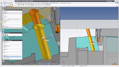
After: Adding a screw with automation. Software automation allows the designer to capture the manufacturing process so that users can locate and identify the screws more quickly. For example, positioning a screw right off the center of a cavity block off the back face of the plate, select the face to which you want to attach the screw and the software then automatically picks the right length.
When the engineer validates the inclusion of the component, the automation takes it a step further. It puts in every standard drilling that the component requires while maintaining the company’s standard clearance policies. This automated process takes 20 seconds. Now, let’s make a change to the screw diameter using automation. Because software automation captures the thickness of the plate, all it must do is change the sizes and clearances. Again, this takes only about 10 seconds.
In an automated world, 20 seconds to include a screw versus 180 seconds is considerable time savings. For example, when there are 100 screws in a given design, you have 2,000 seconds or 33 minutes’ worth of work using automation against 18,000 seconds, or approximately five hours of engineering time on screws alone. Of course, no one wants to consider the time wasted putting screws into a design when quoting a job, but this is reality when a shop does not use an automated platform.
Software automation can minimize or altogether avoid mistakes while ensuring stability and predictability.
Downstream Effect
When companies are not working to real standards, there can be an adverse effect on downstream manufacturing. For example, if the engineer enters a clearance of 0.06 inch on a hole for a 9/16 diameter socket head cap screw, the resulting drilling is now 0.6225 inch. As we all know, there is no such standard drill for this.
So, when the shop runs automated drilling in any CAM software that looks for that diameter drill, it’s going to fail. The engineer meant to add 1/16 (0.0625 inch) but instead typed in 0.060, assuming the manufacturing team will understand that they really meant 1/16.
This is old-school thinking and that worked 20+ years ago when most of the manufacturing was done by hand, or if on a CNC, by manual G-code programming. However, today most mold manufacturers use CAM software to program their machines.
When engineering makes assumptions that software cannot understand (because it’s a failure in math), you slow down manufacturing and cause potentially expensive problems. However, if you take a half-second to add the missing two digits, you’ll have a real number and the downstream automation works.
The team just needs to type in the real value. After that, most CAM software on the market can automatically handle the drillings using whatever automation they provide. The best part of this is that if you apply this type of automation or automation thinking to the front end of engineering, you eliminate delays downstream in the manufacturing process and even potentially eliminate the possibility of mistakes.
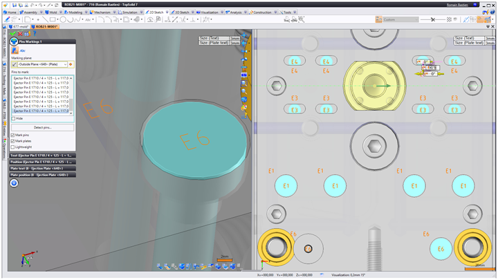
A pin marking feature can be used to identify the pins by applying a marking on the head and the housing of the pin on the ejector plate, minimizing the risk of errors during assembly.
Let’s consider ejector pins that have about eight to 12 key factors for which you must consider clearances — clearances through all the plates, trimming the pin to the molding detail, keying the pin, putting in the correct live travel, et cetera. There are numerous areas where an engineer must make a decision.
Compared to a socket head cap screw, an ejector pin is far more complicated. Without automation, it could take an engineer 10-15 minutes to put one ejector pin into the assembly and apply all the drillings, trimmings and clearances to everything. But suppose you automate the typical process for including ejector pins into a mold design. In that case, you streamline and speed up the design process and likely remove the possibility of costly mistakes again.
The system should be smart enough to look at the geometry and trim the pin automatically to the 3D details. It should automatically determine if they need to be keyed. The process of putting in 10 pins should happen instantly and effortlessly. With proper automation, it should only take about 10-15 seconds per ejector pin or roughly between 1.5 to 2.5 minutes. Now imagine a mold design that has 300 pins! This is why automation exists.
Many things can be automated in the world of mold design, whether it’s standard components from standard suppliers or your own processes, as many customers have their ways of doing side actions, lifter assemblies or mold straps. So, take the time to teach your way to the software, so it captures the manufacturing process that goes with it. Then, let your designers work on the things that matter.
Related Content
Technology Roundup: New/Improved Technologies You Don't Want to Miss
With all the technology joining the market, moldmaking is a versatile, ever-evolving industry. As such, this technology roundup has no specific theme — it features a variety of products for applications and solutions across the industry.
Read MoreMachine Hammer Peening Automates Mold Polishing
A polishing automation solution eliminates hand work, accelerates milling operations and controls surface geometries.
Read MoreMMT Chats: Eliminating the Noise to Stay Focused on the Customer
Metro Mold & Design joins me to discuss the value of the 80/20 rule as a business strategy, its talented cross-functional team, the role of automation in mold building and molding, and the continuing impact of COVID-19.
Read MoreDynamic Tool Corporation – Creating the Team to Move Moldmaking Into the Future
For 40+ years, Dynamic Tool Corp. has offered precision tooling, emphasizing education, mentoring and innovation. The company is committed to excellence, integrity, safety and customer service, as well as inspiring growth and quality in manufacturing.
Read MoreRead Next
Managing all That Data
Product data management may have a bad rap, but making it a priority rather than an afterthought can help make the most of your design and machining information.
Read MoreCAD/CAM Upgrade Boosts Shop’s Efficiency
CAD choice automates and animates, builds customer confidence through communication, and cuts design time in half.
Read MoreHow to Use Strategic Planning Tools, Data to Manage the Human Side of Business
Q&A with Marion Wells, MMT EAB member and founder of Human Asset Management.
Read More


