How to Better Balance Family Molds
A servo-driven valve gate can provide superior processing for family molds with significant variances in part sizes and volumes.
Family molds, which allow plastic processors to create different parts in a single mold, offer great advantages regarding lowering total tooling budgets and managing work-in-progress (WIP). Historically, family molds present inherent challenges and require expertise to balance material within the multiple cavities properly. With traditional control methods, all cavities are processed using common parameters set at the injection piston. So, the parts in a family mold customarily need to be very similar in size, weight, wall section and volume.
However, using servo valve gate technology to control the process for each cavity individually directly at the gate can eliminate this constraint. The molding operator can control the stroke, velocity and force of each individual pin independent of one another. The resulting pressures, flow rates and volumes of the melt in the cavity are controlled at each gate independently, which means that each cavity or gate can have its own process (fill speed, fill pressure, pack pressure, pack time). This precise control can prevent overfeeding and flash formation on different-sized parts while all cavities are filled simultaneously.
This precise control can prevent overfeeding and flash formation on different-sized parts while all cavities are filled simultaneously.
Proving it Out
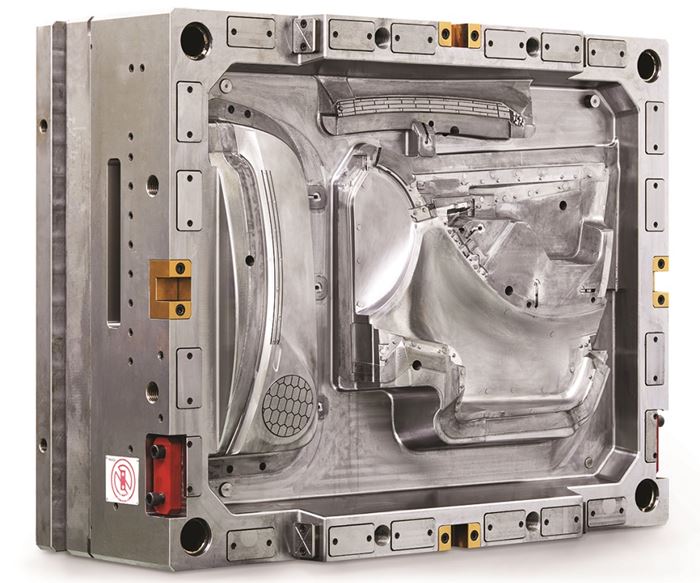
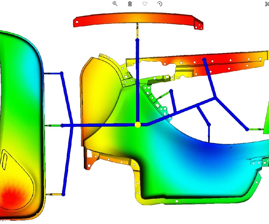
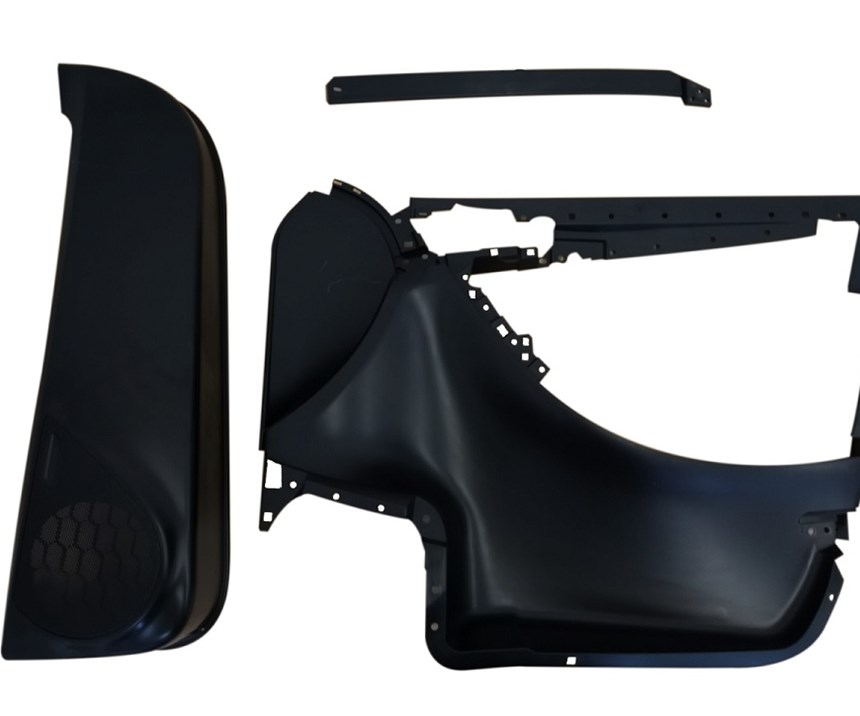
The demonstration family mold pictured above was made with three different weights and volumes to prove out the capabilities of a servo-driven electric valve gate system. The polypropylene parts include an automotive door panel (560 cm³), map pocket (338 cm³) and reinforcing bar (58 cm³) with wall thickness ranging between 2.3 mm and 3 mm.
Engineers designed the 1190 mm x 950 mm x 851 mm, 6530-kg mold to process propylene and ABS in an injection molding machine with a 10,000 kN clamping force. The processor obtained information about the mold-filling process from two pressure sensors located in each large cavity and the small cavity, while six contact sensors provided mold deflection data during the injection phase.
Engineers equipped the mold with an eight-nozzle, electrically-driven valve gate hot runner system designed for sequential injection molding. The aligned nozzle openings, permitted by electric technology, alleviated the pressure loss that often occurs during injection molding and eliminated any surface marks. Precise control of nozzle pressure during the holding pressure phase improves part quality in each cavity. The cycle time to produce the three parts was approximately 55 seconds.
This servo-driven solution can help maximize efficiency and decrease costs of a family mold with large part variances.
About the Author
Sergiu Fatu Ph.D is an engineering manager for HRSflow North America.
For More Information
Related Content
-
Industry Report: Automotive Outlook, Forecast, Disruptions and Industry Transitions
A recent presentation by Auto Forecast Solutions shares some interesting trends to help those who work within the automotive industry better understand key trends.
-
Project Reveals Added Benefits of New P20 Grade Steel in Machinability, Cycle Time and No Stress Relief
MoldMaking Technology's Christina Fuges talks with General Motors' Shane Appel about a project testing a new P20 steel grade's dimensional stability.
-
Hot Runner Technologies Advance Quality Surface Requirements in Automotive
Oerlikon HRSflow hot runner systems combine cost-efficient production with a precise process control for a variety of automotive applications.


