Today, a shop can get the required functionality from inspection/measurement systems without spending more than necessary. The challenge is striking the right balance between a shop’s needs and the overall equipment costs. While the price of a system may be the only fully definable cost at the time of purchase, determining the best option involves accuracy, flexibility, speed, efficiency and ease-of-use considerations, which can have financial ramifications directly affecting the total cost of ownership and operation.
Accuracy
Accuracy is an essential consideration. For example, accurate identification of conforming and out-of-spec parts maintains quality, protects the integrity of the entire production process and reduces scrap rates. Protection from temperature fluctuation and shop floor conditions enables inline installation, reducing the cost and delay of transporting parts for testing and enabling faster identification and correction of production problems.
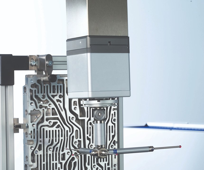
The necessary degree of accuracy can vary depending on the application. A system’s capabilities should match current and future needs. However, accuracy is not a uni-dimensional metric like horsepower. A system’s accuracy depends on how one uses the system. This includes the sensors necessary to measure the workpiece, the workpiece shape, the angle at which the system must approach the workpiece, the required probe length when working in deep holes and more.
Many factors contribute to a system’s accuracy, including its design and construction. For example, resistance to temperature fluctuation, which can be affected by design, material choices and insulation, ensures that measurements are both accurate and consistent. It can also reduce or eliminate the need for mathematical compensation and make it possible an operator to install the system on the shop floor rather than in a costly, often remote or environmentallycontrolled lab.
The rigidity of the system components also helps ensure that the operator is measuring the workpiece and not the flex in the measuring system. Fixed component rigidity is relatively simple and straightforward, but moving elements make it more challenging.
Fixed component rigidity refers to the stiffness of the measuring equipment’s frame. For example, the frame holding the table and detector inside a computed tomography (CT) machine, which can measure a mold. The more rigid the frame, the lower the source of measurement errors. Moving elements, such as a rotary table that holds a mold or an articulating probe head in a coordinate measuring machine (CMM), make it more challenging. The heavier the moving part, the higher the inertia of motion that challenges the ability to precisely control its position during measurement.
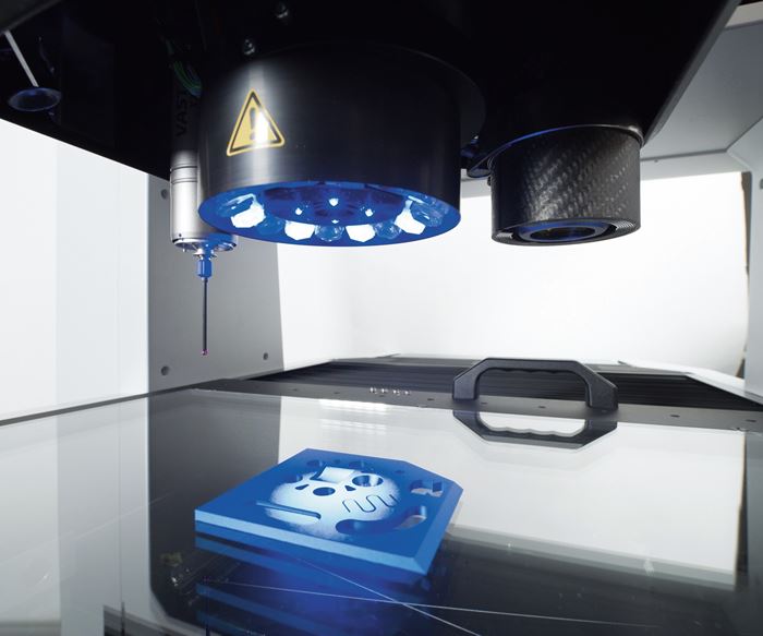
Measurement technologies available today are many, but each has its place. For example, plastic injection molding requires CT technology (like an MRI scan) to accurately see and measure a mold’s inner dimensions. Or, automotive powertrain applications require the most accurate tactile measurements for checking surface roughness and bore smoothness of engine blocks. And, medical device manufacturers require non-contact optical technology to measure three-dimensional shapes of artificial knee and hip joints. If the measurement at hand is specific, limited and unlikely to change, then a single-technology machine may be all that is required. On the other hand, if the shop’s needs vary (or may change in the future), the ability to support multiple technologies will be critical.
Rigidity of system components also helps ensure that the operator is measuring the workpiece and not the flex in the measuring system.
Flexibility
A multi-function measurement system enables a shop to maximize the return on its investment. For example, a flexible system enables right-sizing of machines, eliminating the cost of wasted capacity. A flexible system performs tactile, optical and laser measurements with the same base system, eliminating the cost of multiple machines, and a flexible system scans unknown contours, eliminating the cost of sending parts out for reverse engineering. And, it reduces the need for stylus changes or offers a quick-change capability, increasing throughput.
It is important to ensure that the measurement system has the range and level of functionality required. Consider the maximum measuring volume that the machine can accommodate. A too-small system will not handle bigger parts, but a too-large system takes up space and capital that could be put to better use. Look for equipment that can “right-size” without sacrificing necessary capabilities.
Measuring methods are another consideration. Tactile and optical techniques each have their place, and if one machine can do both well, it will yield effective measurements across the board without having to buy two machines. The system should also accommodate a range of tactile sensors. The wider the range a system can handle, the more flexibility it will provide.
Consider sensor size, the angles at which they can operate and scanning heads that offer electronic rather than spring buffering for maximum speed and accuracy. Active scanning technology makes it possible for unknown contours to be scanned, which can be particularly useful for reverse engineering tasks. For optical sensors, consider the granularity of measurement—smaller is better—and look for a choice of measuring ranges to maximize accuracy when measuring parts of different sizes. If laser scanning for extremely fast measurements of freeform workpieces is required, look for a system that offers that option.
Keep in mind when considering add-on components like more sensors, fixtures or application-specific measurement software (to increase system capabilities), that they must work together to be effective. While it is sometimes possible to integrate components from different manufacturers into a single system, the more manufacturers that are involved, the more complicated that process can be. This applies both to initial integration and to ongoing operation and support. Working with a supplier that has a full range of multi-function systems and add-on components that can be purchased later is often the best approach.
It is important to ensure that the measurement system has the range and level of functionality that is required.
Speed
In some cases, increased accuracy can be “purchased” by slowing down measuring operations and reducing throughput. That may be acceptable when time is not an issue, but when throughput is important, sacrificing speed to achieve accuracy is not an option. Slowdowns in measurement can slow down the entire molding or machining process. The right speed helps maximize throughput, which reduces labor costs and eliminates the need for additional machines to keep up with the workload.
For example, a CT system will be faster and more accurate when measuring a plastic injection mold’s critical dimensions than a tactile measuring system because the CT approach captures dozens of measurements at the same time. When measuring CNC-machined parts, a CMM using active scanning will be faster and more accurate than “spot checks” of a touch-and-go system. Once scanning has started, a system’s ability to “fly over” gaps in a contour can shorten programming time and speed up measurements. For example, this can speed up measurements when scanning over bore holes, scanning teeth of a gear wheel or scanning an interrupted plane.
Depending on the measurements being done, these capabilities can significantly shorten per-part run times and can reduce the number of machines needed to handle the workload in a busy shop. As with many “high-end” capabilities, this feature was initially available only on the most expensive systems but is now working its way down to more economical systems.
Efficiency and Ease of Use
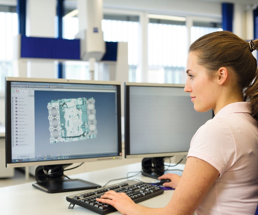
Metrology systems are getting smarter all the time, but people still run them. The machine’s intelligence, in the form of software, has a significant impact on ease of use and that level of operator experience that is required. For example, faster programming and visual presentation of results can speed up the start and completion of operations. Look for measurement software that can automatically create a measurement program from a 3D CAD model. In mold applications, this approach can often reduce the necessary time to create a measurement program from weeks to hours.
This approach can often reduce the necessary time to create a measurement program from weeks to hours.
An intuitive system with a touch screen and a user-friendly display requires less training and less operator expertise. It also can reduce setup time for experienced and less-experienced users alike. Characteristic-based software enables programmers and operators to easily maneuver through measurement plans. User-oriented features like the ability to visually superimpose actual measurements over design specifications help eliminate both out-of-spec parts and unnecessary scrapping of acceptable parts. And, if using a variety of machines, the ability to use the same measurement and quality data management software across multiple systems shortens setup time and cuts training costs.
Efficiency can be found in some unexpected places too. Many systems use compressed air to reduce friction, and while air may be free all around us, the stuff in tanks costs money. An option that reduces compressed-air use can quickly pay for itself. And, local availability of factory-trained service can help ensure that problems are addressed quickly and effectively to keep equipment operating at peak efficiency and to keep it correcting faults as quickly as possible, which reduces downtime.
Finding the most economical inspection/measurement system to meet a shop’s needs does not need to be complicated. It begins with identifying current priorities and anticipating future requirements, factoring in the costs of labor (including setup and operation), possible downtime, air and other incidentals and then comparing the options with demanding, hands-on demonstrations.
About the Contributor
David Wick
David Wick is the manager of product management at Carl Zeiss Industrial Metrology LLC.
Related Content
VIDEO: Maintaining a Customer-Centric Culture
Progressive Components President Glenn Starkey talks about the importance of the customer and culture when developing technology solutions for the moldmaking industry.
Read MoreSoftware Strategy for Automated Mold Inspection
Consider inspection software with a CAD/CAM platform that supports model-based definition, works with all CAD files, and drives all fixed and portable CMMs.
Read MoreHow to Achieve Automated Measurement With Advanced Touch Probes and Laser Systems
A combination of lasers, probes and software help moldmakers automate in-process cutting tool and workpiece measurement.
Read MoreCT Scanning Helps Micro Molder Reduce Cost of First Article Inspections
CT scanning services performed by 3D ProScan, a division of NyproMold Inc. provides MTD Micro Molding with accurate, high-resolution internal and external measurements performed about seven times faster and at significant cost savings.
Read MoreRead Next
How to Use Strategic Planning Tools, Data to Manage the Human Side of Business
Q&A with Marion Wells, MMT EAB member and founder of Human Asset Management.
Read MoreAre You a Moldmaker Considering 3D Printing? Consider the 3D Printing Workshop at NPE2024
Presentations will cover 3D printing for mold tooling, material innovation, product development, bridge production and full-scale, high-volume additive manufacturing.
Read MoreReasons to Use Fiber Lasers for Mold Cleaning
Fiber lasers offer a simplicity, speed, control and portability, minimizing mold cleaning risks.
Read More


