A Simple Way to Improve Communication with the Shop Floor
Generating set-up sheets, in-process inspection instructions and other documentation from simulated in-process machined features improves communication, saves time and increases accuracy.
Mistakes on the shop floor are expensive, and it is critical that the machine operator and NC programmer communicate effectively. The implications of poor communication go well beyond wasted programmer and machine time. Something as simple as a poorly defined set-up instruction sheet can result in scrapped parts, broken cutters or a damaged machine. Worse yet, a late delivery can result in the loss of future business. When all of these risks are combined, it’s difficult to quantify the value of good communication.
There are many benefits of accurate and detailed shop reports. In addition to avoiding the costly risks already mentioned, good reports increase operator confidence, requiring less babysitting of the NC machine, and less reason to turn down the feedrate. Good reports improve communication and reduce production time by providing clear instructions. They can help to formalize what is already being done and provide timely information that accurately represents the real process across all departments. Good reports can also be provided to customers, helping to establish or maintain a positive reputation.
There are many ways moldmakers currently create inspection instructions and other reports. Some moldmakers create shop documentation using an Excel spreadsheet and screen captures from their CAD/CAM software. But many reports require an “in-process” model. Creating these models in a CAD system is a manual process that requires a certain degree of technical expertise and engineering time. Not only is it time-consuming, it is prone to error and redundant. Many moldmakers are unaware that they can simply use their NC simulation software to automatically generate the necessary reports for them.
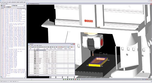
Many moldmakers already rely on simulation to prevent costly mistakes from getting to the shop floor. By simulating the post-processed code (G-code), the NC programmer can spend less time visually proving out the data. The simulated cut stock can also be compared to the design model, ensuring the NC part meets design model specifications.
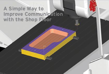
NC simulation software is the key to automatically generating shop documents because an in-process model of the part is created during simulation. When a simulated model has been created from the actual geometric data from G-code, there is no need to create an in-process model in a CAD system. Creating shop documentation can be quick and easy to automate, thereby significantly reducing engineering time.
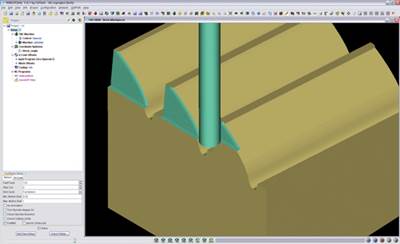
For example, the NC programmer can see and report the part in the as-machined condition, as opposed to the direct net requirements. Reports can be created during roughing operations that leave stock material, and the operator can then see exactly how much—and where—material remains. These types of reports are very useful and appreciated by both the shop and QA.
There is an almost unlimited number of reports that can be automatically created using NC simulation software. The layout of each report is completely user-configurable with a simple user interface. Using information from the simulation session, pictures, operator instructions and other information can be automatically generated and inserted into the report.
No programming is required and the reports can be output in HTML or PDF format. For example, set-up sheets with dimensions can help operators ensure that each set-up is correct. And when working with multiple set-ups, it is very helpful when the set-up sheets show the in-process state of material.
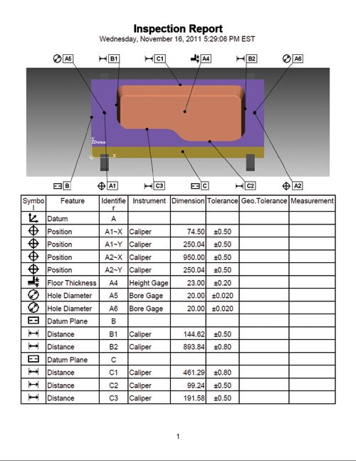
The Quality Assurance department can also benefit from reports generated from the NC program. A significant percentage of manufacturing time is spent inspecting the workpiece. The user can simply click on cut model features in the simulation to create in-process inspection sequence instructions. The software will automatically identify where and what to inspect.
For the ultimate reporting capability, Moldmakers can now go beyond 2-D reports by using a free 3-D simulation reviewer. Previously an operator would need to visit the programming office to view a program being simulated. But now it is possible to create and save a reviewer file at any point in a simulation session. The saved file can then be sent to the shop floor. By using a stand-alone reviewer, shop supervisors, technicians, machinists and machine operators can review a 3-D machine simulation of the NC program without leaving the shop floor.
The 3-D reviewer is a very powerful tool that also helps improve communication with customers, suppliers and anyone else who can benefit from having access to a 3-D simulation. The user can play the 3-D simulation forward and backward to see material being removed or replaced. Error messages and NC program text is highlighted when a collision on the stock or fixture is selected.
Cutting conditions and a toolpath line display can be optionally shown. The user can rotate, pan and zoom, and the cut stock can be measured using a variety of measurement tools.
Creating reports is a required process for any moldmaker, and generating set-up sheets, in-process inspection instructions and other documentation from simulated in-process machined features saves time and improves accuracy. And moldmakers looking to cut down on paper reports are no longer limited to a 2-D world. A 3-D simulation review file can eliminate virtually any surprise, in a virtual world.
Related Content
How to Use Scientific Maintenance for More Accurate Mold and Part Troubleshooting
Discover how adopting scientific maintenance approaches helps improve mold lifespan, minimize failures, and optimize production outcomes.
Read MoreWhat is Scientific Maintenance? Part 2
Part two of this three-part series explains specific data that toolrooms must collect, analyze and use to truly advance to a scientific maintenance culture where you can measure real data and drive decisions.
Read MoreHands-on Workshop Teaches Mold Maintenance Process
Intensive workshop teaches the process of mold maintenance to help put an end to the firefighting culture of many toolrooms.
Read MoreDynamic Tool Corporation – Creating the Team to Move Moldmaking Into the Future
For 40+ years, Dynamic Tool Corp. has offered precision tooling, emphasizing education, mentoring and innovation. The company is committed to excellence, integrity, safety and customer service, as well as inspiring growth and quality in manufacturing.
Read MoreRead Next
Machine Verification Software Slashes Leadtimes, Builds Confidence
When Tri-Mack Plastics Manufacturing Corp. (Bristol, RI)—a manufacturer of high-performance components for critical applications primarily for the aerospace industry—was looking for the least expensive way to cut leadtimes, verify cutter paths, and virtually inspect their cut parts, all without sacrificing quality, the company turned to CGTech/Vericut software (Irvine, CA) to accomplish these goals.
Read MoreHow to Use Continuing Education to Remain Competitive in Moldmaking
Continued training helps moldmakers make tooling decisions and properly use the latest cutting tool to efficiently machine high-quality molds.
Read MoreHow to Use Strategic Planning Tools, Data to Manage the Human Side of Business
Q&A with Marion Wells, MMT EAB member and founder of Human Asset Management.
Read More


