A CAD-for-CAM Toolbox Helps Moldmakers Design Better Molds
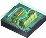
An important CAD function that a CAM package should offer moldmakers is a set of specialized CAD-for-CAM tools that focus on the machinist’s needs after the machinist opens the part file.
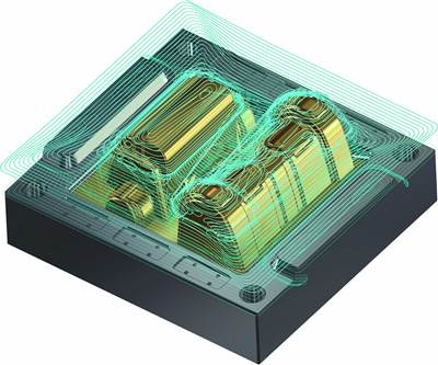
CAD-for-CAM tools streamline toolpath generation and frequently promote better part finishes.
Photo Credit: CNC Software
Most part-manufacturing processes today begin with a CAD model rather than a print. For subcontract mold shops, it may be the finished part model file that comes in from the customer’s design staff. Then, it is the moldmaker’s turn to construct the CAD model of the mold that will form the finished plastic part. That has its own inherent challenges because moldmakers have many things to think through about the mold, which the part designer may not consider. One of those things is part removal.
Most CAM software packages can accept a wide variety of specific or neutral CAD file types. Many also have a robust CAD engine of their own, giving the user the ability to create the model from scratch, if necessary. CAM software packages also provide a number of tools to easily adjust the CAD file. However, one of the crucial CAD elements that a CAM package can offer moldmakers is a set of specialized CAD-for-CAM tools that focus on the machinist’s needs after the machinist opens the part file.
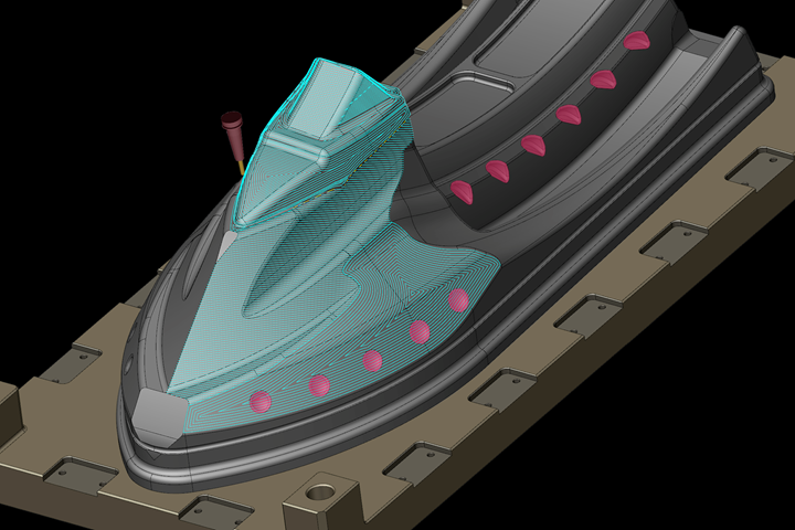
CAD-for-CAM tools enable quick, temporary model changes that do not impact the final part design but can streamline toolpath generation and frequently promote better part finishes. These often start with the ability to “heal” flawed surface or solids data, making the part usable.
Other tools are geared towards temporarily filling holes or shallow pockets, and identifying solid-model features that the machinist can quickly turn “on” or “off” in the CAM package for programming purposes. This can make the cut over an entire part smoother before those details are machined and help yield a better, higher-quality finish at a faster pace.
Parting line calculation is crucial in ensuring that the mold is sectioned properly. Good CAM software will offer the ability to calculate optimal parting lines from the CAD model, which is something that the part designer often does not consider.
Other powerful CAD-for-CAM tools focus on the creation of the mold itself. Parting line calculation is crucial in ensuring that the mold is sectioned properly. Good CAM software will offer the ability to calculate optimal parting lines from the CAD model, which is something that the part designer often does not consider. Similarly, tall, thin elements on a molded part can pose challenges to the machinist, who has to try to separate areas where electrodes might be appropriate. Automated CAM tools that automatically pull EDM electrodes from a CAD model make the process much faster and more precise.
As a general rule, designers are more focused on the nuances of the finished part, while CAM programmers, manufacturing engineers and machinists concern themselves with making the part, and the first step is the mold. That is no small feat either, and machinists often need to be every bit the artist that a designer has to be to manufacture a good mold. Happily for moldmakers, excellent tools in CAD/CAM packages are available that make the job easier.
About the Contributor
Ben Mund
Ben Mund is a senior market analyst at CNC Software/Mastercam.
Related Content
Mold Design Review: The Complete Checklist
Gerardo (Jerry) Miranda III, former global tooling manager for Oakley sunglasses, reshares his complete mold design checklist, an essential part of the product time and cost-to-market process.
Read MoreHow to Fix Predicted Warpage Before It Happens with Windage and CAD Model Morphing
Applying windage and model-morphing techniques saved toolmaker/molder Sturgis Molded Products the time, cost, headaches of multiple part/mold design iteration loops, cumbersome cooling fixtures, and long molding cycles.
Read MoreCAM Code Is Key to Precision Mold Machining
The intuitiveness of Mastercam’s CAD/CAM interface streamlines training and advanced programming for intricate fishing tackle products from Venom Outdoors.
Read MoreFour Micro Tooling Considerations
Issues involving gating, ejection, mold splits and direction of pull are of special concern when it comes to micro tooling.
Read MoreRead Next
Leveraging CAD/CAM Advances
Often-overlooked software tools can enhance moldmaking business competitiveness.
Read MoreHow to Use Continuing Education to Remain Competitive in Moldmaking
Continued training helps moldmakers make tooling decisions and properly use the latest cutting tool to efficiently machine high-quality molds.
Read MoreReasons to Use Fiber Lasers for Mold Cleaning
Fiber lasers offer a simplicity, speed, control and portability, minimizing mold cleaning risks.
Read More
