Software Product Line Update Includes File Translators, Measurement and Visualization Features
Kubotek3D announced the 2.0 release of the K‑Compare CAD file discrepancy reporting and K-Display MCAD visualization software products.

Kubotek3D announced the 2.0 release of the K‑Compare CAD file discrepancy reporting and K-Display MCAD visualization software products. This release includes the maiden version of the K-Compare Revision product for creating reports detailing the differences between two versions of the same CAD model. The other three products in these product lines have been enhanced since their last major release with eight updated CAD file translators and several new measurement and/or visualization functions.
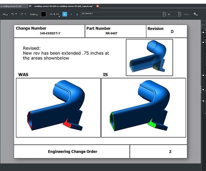
The K-Compare Revision product is a significant new addition to Kubotek’s line of CAD utility programs built on the Kubotek Kosmos 3D framework introduced last year. The Revision product automates portions of the process for engineers documenting a change to a part. K-Compare Revision software enables its users to identify all changes to the model and data, communicate detailed understanding of changes to all stakeholders, handle design files from any major source and quickly create complete reports.
All four K-Compare and K-Display 2.0 software programs offer updated support for the latest versions of major CAD file formats. K-Display 2.0 products also include added support for industry Foundation Classes version 2x3, 2x4 and CATIA CGR lightweight 3D mesh files, all versions.
A simple cutting plane function has been added to K-Display products which enables users to visualize the interior sections of complex parts. Additionally, the wireframe display mode has been enhanced to include silhouette edges which improves visualization of part geometry. Two new measurement functions have been added to K-Display products which are important for engineering or production cost estimation. The first new function analyzes 3D models of plastic parts to find areas which are difficult or impossible to create with a simple mold strategy. The other new measurement function supports quick overall measurements of the envelope of selected 3D models by wrapping them with temporary “bounding box” solids. The ability to quickly measure the angle between two linear edges of a model is also now available in all four products.
The ability to compare folders of part files and assembly files which include references to part files has been enhanced since the initial major release. These features enable users comparing a large batch of files to line up corresponding pairs of files into horizontal rows to simplify visualization. Comparison of PMI annotation (3D feature control frames) has received a significant upgrade to include testing of the associative connection to model faces and semantic style testing of the tolerance type and values within control frame. Validation PDF reports have an added option to include an automatic image capture of the region of the parts where each difference has been detected, with the faces found as different highlighted.
Free trials of Kubotek software are available.
Related Content
-
What Is Scientific Maintenance? Part 1
Part one of this three-part series explains how to create a scientific maintenance plan based on a toolroom’s current data collection and usage.
-
How to Manage Wall Thickness Changes in Your Mold Design
To ensure even filling and cooling, consider wall section transitions, corners and fillets, ribs and bosses, lip and rim designs and CAE flow simulation software.
-
Tolerancing in Mold Design, Part 2: Using GD&T to Address Conventional Tolerancing Issues
Mold designers can achieve a single interpretation of workpiece functionality when following the American Society of Mechanical Engineers Geometric Dimensioning and Tolerancing standard.


