Is the Part Design Good?
Basic part design is always a concern and is the starting point for a robust process that is profitable.
n this article we will take a very general look at some of the most basic design requirements (constant wall thickness and draft) and possibly make recommendations to help us build a better mold with more success.
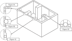
The first is constant wall thickness throughout the entire part—such as at wall junctions, where bosses are attached, ribs, etc.—as shown in Figure 1A through D in which a circle is used to find thick sections that offer the opportunity for processing and quality problems. The goal would be to have all circles the same size at all areas of the part, including corners and wall junctions. Many times this is not possible, although knowing this we can now plan the mold steel, water lines and ejection so that the areas of concern can be managed.
Figure 1A shows a corner view. In this view we can see the circle in the corner is larger than the circle in the wall area. The opportunity for sink will exist where the apex of the circle contacts near the outside corner. A void or voids will exist in the center area of that same circle. To improve this area, use the radius on the outside and inside instead of a square corner. Also, an inside square corner is a stress concentrator for the plastic as it travels around the sharp edge. Another concern is the cooling capability for the inside of the corner compared to the outside. There will be more cooling available for the outside than the inside—thereby creating two different cooling rates for that wall area. This is more significant with semi-crystalline material.
Figure 1B shows the attachment of a thicker wall, which in many ways is not very different than Figure 1D. Many of the same concerns apply as previously discussed. Inside sharp corners, stress and cooling concerns will still exist.
Figure 2A through C shows some alternatives to the additions to a wall not yet limited. Figure 2A shows the addition with a core out. The new problem now becomes, “Can that core be cooled fast enough or at all, especially for a fast cycle time?” Figure 2B is a better choice if you need to maintain a thicker wall addition, using circles again to validate any thick sections. Narrower multiple additions shown in Figure 2C could be even stronger if applicable.
Figure 1C shows an area in which the wall thickness is enlarged. Note that the circle becomes larger, illustrating a non-consistent wall thickness. For processing (packing the thick section out without over-packing the thin section) and gate location (whether you want to fill from thick to thin or thin to thick), this will cause problems and possibly make it difficult to achieve consistency. Again, there will be two different shrink rates and cooling rates in those areas. If voids exist you will need to increase pack or hold depending on the style of molding being done, which may make the thinner section too big or oversized (more molecules pushed into an area means less room in which to shrink).
Another area that should be planned for is draft. All walls should have draft. Two degrees draft makes release of the part very good. Anything less will start offering challenges unless mold steel can be moved away via CAM.
Related Content
The Role of Social Media in Manufacturing
Charles Daniels CFO of Wepco Plastics shares insights on the role of social media in manufacturing, how to improve the “business” side of a small mold shop and continually developing culture.
Read MoreMaking Quick and Easy Kaizen Work for Your Shop
Within each person is unlimited creative potential to improve shop operations.
Read MoreSteps for Determining Better Mold Prices
Improving your mold pricing requires a deeper understanding of your business.
Read MoreDynamic Tool Corporation – Creating the Team to Move Moldmaking Into the Future
For 40+ years, Dynamic Tool Corp. has offered precision tooling, emphasizing education, mentoring and innovation. The company is committed to excellence, integrity, safety and customer service, as well as inspiring growth and quality in manufacturing.
Read MoreRead Next
A Specialized Mold Design Strategy
Solving complex mold design challenges with specialized CAD software.
Read MoreHow to Use Continuing Education to Remain Competitive in Moldmaking
Continued training helps moldmakers make tooling decisions and properly use the latest cutting tool to efficiently machine high-quality molds.
Read MoreReasons to Use Fiber Lasers for Mold Cleaning
Fiber lasers offer a simplicity, speed, control and portability, minimizing mold cleaning risks.
Read More
