Under the Scope: Shielding the Weld
It is important for every welding novice to understand both the dangers of oxygen contamination in the welding process and the use of a shielding gas to protect the weld (either TIG or laser) from oxygen contamination.
It is important for every welding novice to understand both the dangers of oxygen contamination in the welding process and the use of a shielding gas to protect the weld (either TIG or laser) from oxygen contamination.
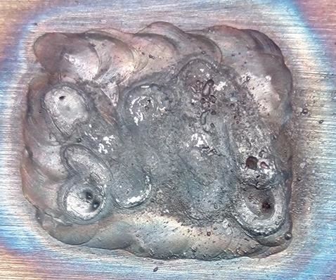
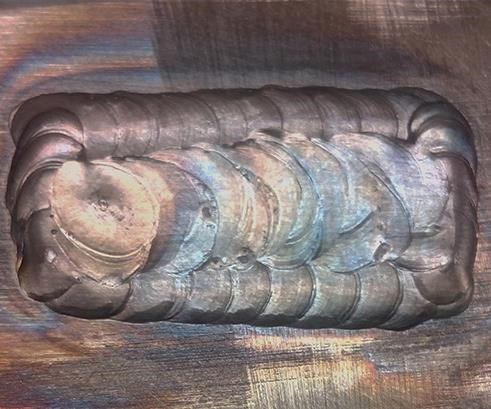
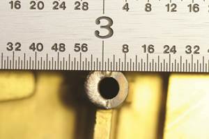
Oxygen contamination. Exposure to oxygen during the welding process compromises the chemical composition of a weld, making it appear grey and porous. To protect the weld from oxygen, a shielding gas is used to form a chamber around the weld that blocks out any atmospheric contamination. Figure 1 shows an area welded without a shielding gas, and Figure 2 shows one welded with a shielding gas.
Clearly, the weld in Figure 1 is ascetically unpleasing, but it also is structurally weak and would fail inspection. The shiny, clean and porosity-free appearance of the weld in Figure 2 is a result of a properly applied shielding gas. Even the slightest corruption by oxygen can be problematic, as it will cause porosity.
Shielding gas. A shielding gas is essentially an inert gas. This means it has low reactivity when exposed to other atmospheric elements. The shielding gas typically used in micro-TIG (tungsten inert gas) and Nd:YAG (neodymium yttrium aluminum garnet) laser welding for mold repair is argon. Argon is an excellent shielding gas because, as it is distributed during a welding process, its heavy density helps push away oxygen from the weld zone. Argon’s high ionization capability also helps a TIG torch start efficiently.
In laser welding, a shielding gas also stops plasma from forming on a weld, which can lessen the laser’s power and diminish weld quality. In my experience, pure argon delivers a cleaner weld than a mixture of other inert gases.
Shielding gas delivery. The method for delivering a shielding gas to the workpiece is dictated by the welding process, but both micro-TIG and laser welders can use a special cylinder tank (supplied by a specialty gas company) that is connected to a pressure regulator and then to the welding machine through a hose.
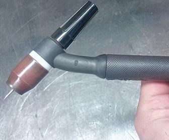
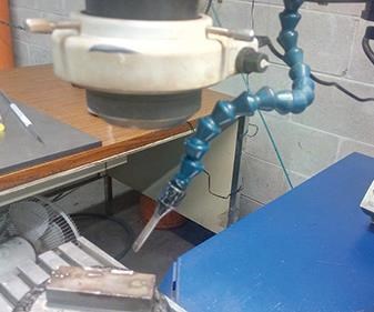
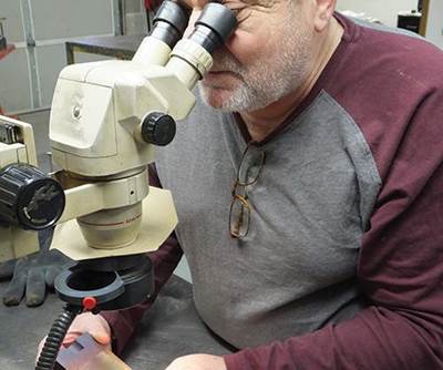
Figure 3 shows a TIG torch in which the shielding gas flows through the torch hose and torch head, spreading evenly across the workpiece. Figure 4 shows a shielding-gas setup for a laser welder. In laser welding, the gas is delivered from a line that is connected to the laser arm, which is manipulated at an angle to the workpiece.
Delivery of the shielding gas must be properly adjusted so that it covers the entire weld during the process. There are certain circumstances—welding in a tight area or on a thin-walled detail, for example—under which the welder would use two shielding gas lines to further protect the area being welded from oxygen.
Shield gas problems. When applying a shielding gas for TIG welding, the welder should consider gas flow rate, position, pre-flow and post-flow. The gas flow rate (amount per hour) must be adjusted properly for even gas distribution. In my shop, for example, the flow rate on the micro-TIG welder is set to 15 to 20 cubic feet per hour (cfh) on the regulator. A common mistake by many novice TIG welders is to increase the flow rate to 40 or 50 cfh, believing that this higher flow will provide even better gas coverage. However, this is not the case. The force of excess shielding gas will actually create a vacuum that drags in atmospheric contaminants.
In my shop’s laser welder setup, the flow rate is set to 2 cfh. This is lower flow than on a TIG welder, because the laser welder has a smaller nozzle, so the gas stream is more concentrated. Special care should be applied to properly angle the shielding gas to the workpiece in laser welding. The nozzle should be positioned in a manner that allows the gas to blow across the pulsed weld puddle without the nozzle blocking or interfering with the pulse.
In TIG welding, the shielding gas pre-flow and post-flow can be adjusted so that the argon is distributed continuously a few seconds before an arc is initiated and after the arc is terminated. This setting helps blow away the oxygen before welding and a few seconds after welding to help the weld cool down before it is introduced it to the environment. Following these procedures will help improve weld quality.
Related Content
How to Use Scientific Maintenance for More Accurate Mold and Part Troubleshooting
Discover how adopting scientific maintenance approaches helps improve mold lifespan, minimize failures, and optimize production outcomes.
Read MoreHow to Use Thermal Management to Improve Mold Cooling
A review of common mold cooling issues and possible solutions, including 3D printing applications.
Read MorePrecision Welding Services Offer Rapid Turnaround Mold Repair and Reduced Molder Downtime
X-Cell Tool & Mold relies on outsourced, high-quality welding repairs from Lewis-Bawol Welding to ensure its customers' molds are back in production quickly and affordably.
Read MoreLaser Welding Versus Micro Welding
The latest battle in finely detailed restoration/repair of mold materials.
Read MoreRead Next
Under the Scope: Mold Repair Workflow
These seven steps can help any shop secure an effective mold repair procedure.
Read MoreHow to Use Continuing Education to Remain Competitive in Moldmaking
Continued training helps moldmakers make tooling decisions and properly use the latest cutting tool to efficiently machine high-quality molds.
Read MoreAre You a Moldmaker Considering 3D Printing? Consider the 3D Printing Workshop at NPE2024
Presentations will cover 3D printing for mold tooling, material innovation, product development, bridge production and full-scale, high-volume additive manufacturing.
Read More
