How to Use Thermal Management to Improve Mold Cooling
A review of common mold cooling issues and possible solutions, including 3D printing applications.
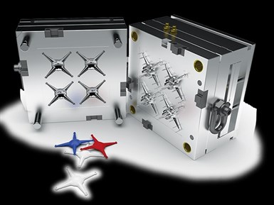
Optimal mold performance depends on a thorough analysis and integration of superior cooling solutions at the point of design. Photos Credit, all images: DME Company
With ever-increasing energy and materials costs, manufacturers are more motivated to improve productivity by streamlining processes, dramatically cutting human resources and budgets and optimizing production processes. For example, shops pay more attention to a mold’s thermal dynamics during design, molding and preventative maintenance (PM) to reduce cycle time, decrease energy consumption, improve plastic part quality and increase yield.
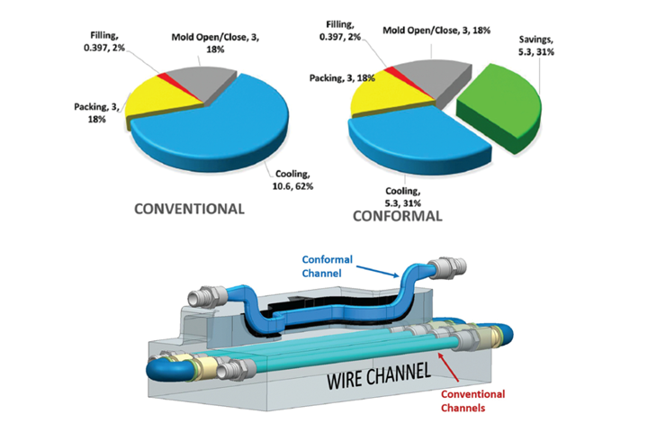
Manufacturers have optimized hot runner systems, gating and finite element method (FEM) simulations to control better fill and cycle times. However, what is rarely discussed is cooling. The cooling cycle can be as much as 70% of a part run cycle, so thermal management to reduce overall cycle times is critical for process optimization. Lower cycle times and lower scrap rates equate to higher part production.
The Cooling Challenge
Adding and removing heat is a fundamental and critical part of the molding process. Most molders and designers are so accustomed to the process that good thermal management practices are often overlooked, and are not always scrutinized the way they should be to optimize the molding process.
With higher expectations on designers and manufacturers and lead times progressively becoming shorter, companies simply cannot afford to ignore any solution that might help create a scenario where optimum part quality, less scrap and less human interaction can be achieved. All of these requirements are now being built into the organization’s production specifications so that no stone is left unturned.
At one point in time, cooling the part surface was generally an afterthought, usually squeezed in with room available after all of the mold design and action components were in place. With this tactic, designers addressed cooling or warping issues after the project went to tryout, sometimes leading to frustration and added cost. Ultimately, these practices resulted in parts that could not be qualified and lead times that could not be met.
Some things may never change when building molds — for example, drilling channels into mold blocks. Designing channels in the cavity (or A side) is easier because outside of the drop or sprue (and some screw holes), there is usually less interference in those plates. The real challenge is the ejector half (or B side) because ejection, lifters, core pins and other components present obstacles to addressing those hard-to-reach areas and keeping the part surface at an even temperature.
When developing a new mold or hot runner system, the design engineer routes the cooling channels to deliver the most effective cooling of the cavity. The goal is to maintain the integrity of the polymer and cool the part to the ejection temperature as quickly as possible. Often the waterlines are gundrilled. This approach can yield suboptimal cooling and a finished mold with a narrow process window, increasing the risk of deterioration in the watercooling line performance over time. The molding process is impacted when the mold temperature shifts from its upper or lower process limits. So, to avoid part quality issues, process conditions may need to be modified.
The calcium impurities of water also impact cooling lines. For example, the oxygen inside the water attacks the mold’s surface, causing corrosion that form “traps” in the cooling channels that capture impurities and create scale. Scale has an insulating effect that significantly reduces heat transfer, forcing a change to molding process variables that often increase cycle times.
Even with the best-filtered water and anti-corrosion agents, cooling channels corrode over the mold’s life. Advanced cooling channel flow monitoring systems reveal this degradation, but current PM programs often have no effective way to correct this.
A robust mold cooling design and a predictive mold maintenance program will yield major benefits and increase the ROI of any molding project.
3D-Printing Cooling and Cleaning Solutions
Today’s sophisticated cooling channel monitoring devices can be a harbinger to detecting cooling channel degradation if they are effectively integrated into manufacturing control processes. They help to monitor the pressure, temperature and flow rate of both the input and return cooling lines, which indicates the cooling process’ stability and verifies efficiency. This method can identify wasted energy and variations in pressure noting blocked waterways, enabling manufacturers to make calculated changes with real data and adjust temperatures and/or pressures to achieve desirable results. Then, when the mold is removed from production, steps can be taken to clean and remove any blockage that may have reduced mold efficiency.
Recent advancements in cooling channel cleaning technology have met this need. The cleaning process must unplug any blocked line by removing debris and descaling the surface of the channels. Traditionally, toolrooms use acids to break down scale to open clogged channels. However, this often perpetuates the problem long-term, as the acid can pit the cooling channel surface, worsening scale buildup.
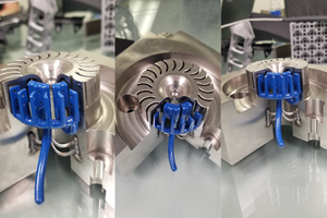
Modern water-based cleaning equipment uses a closed-loop system and a unique pulsating action with heated water to attack a plugged channel from both directions. This approach overcomes an airlock and dislodges the blocking material. A three-component system removes scale and rust: (1) heated water with (2) a mild chemical agent and (3) a pulsating action of the water.
Like mold design, the molded parts also present challenges that hold up cycle time, such as the features of bosses, cores, deep ribs, and lifter and die locks. Conventionally, these features are cooled with baffles or cascades, which can fall short of cooling the entire feature, leading to hot spots.
Cooling is the largest portion of the molding process, so considering alternative approaches, such as conformal cooling, can yield improvements and savings.
However, using direct metal laser sintering (DMLS) and sinter-based additive manufacturing (SBAM) to create these components solves these problems. For example, printing conformally cooled metal inserts — for core features or isolated areas holding up cycle time or affecting the part quality — with elaborate channel designs that allow cooling closer to the part surface. (Note: 3D-printed inserts are also used for heating applications such as connector plugs with high percentages of glass fillers. Higher temperatures are introduced to these areas for a better surface finish for mating conditions.)
This technology can also be used in lifter heads and slide noses. The methods in which we deliver liquid media to lifter systems may vary, but introducing complete cooling coverage to these components effectively shortens cycle time while improving part quality. Slides can also be very limited for cooling via conventional means, but 3D-printed slide noses are highly accessible to provide even cooling.
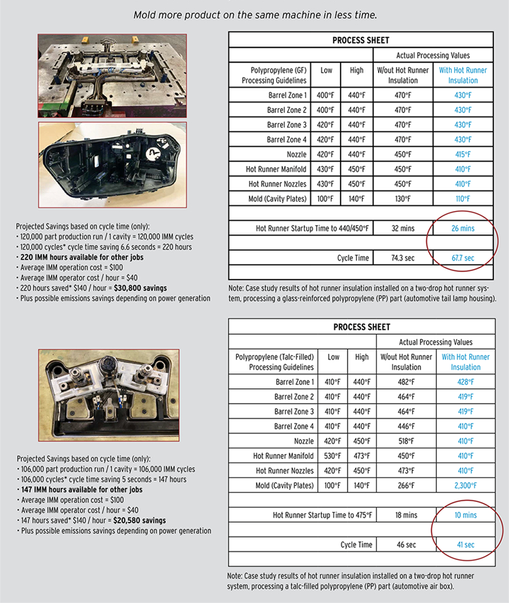
Regarding hot halves, the design engineer intends to route the cooling channels to deliver the most effective cooling of the cavity to maintain the integrity of the polymer. Insulating the hot runner system is a relatively easy and non-invasive way to lower melt processing temperatures, reducing part cooling time and power consumption. Some insulating products are ineffective, while others contain harmful substances. Still, with advancements in nano-microporous insulating materials, great strides have been made in reducing energy consumption and minimizing thermal transfer from manifold systems to mold blocks.
For example, cold spots exist in even the most advanced hot runner systems. The resin is often processed at higher-than-necessary temperatures to prevent freezing in these cold spots. Effectively insulating the hot runner can minimize thermal variation across the system, which in many cases allows the resin to be processed at lower temperatures. Getting the melt into the cavity at a lower temperature means less cooling time to ejection. Case studies have proven that temperature reductions of only a few degrees can significantly impact cycle time, resulting in a less expensive part and increased capacity of the molding cell (see “Case Studies Using Hot Runner Insulation” sidebar).
3D printing also has advanced gating applications. Much time is spent at mold tryouts waiting for the press to open because the material in the sprue has not solidified. Those sprues can now be cooled with conformal bushings, which cools the sprue 40% faster. And conformal gate bushings — designed to target the tip, so the heater bands do not work harder to sustain minimum temperatures — reduce stringing and blemishing.
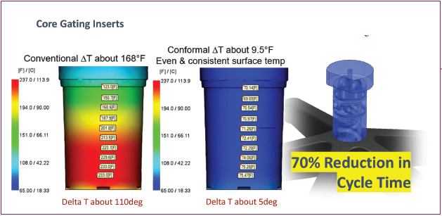
Average cycle time reductions concerning conformal-cooled inserts are about 30% and can be as high as 70%. These higher reductions are enabled more with standing core features. However, this technology has countless practical applications for driving cycle time down.
Plan During Design
Understanding that even a thin layer of scale on a cooling channel can change the thermal transfer to the mold is essential to maintaining consistent process windows over periods of time. Regimented, targeted maintenance can ensure process windows have only slight fluctuation and scrap rates are low.
With pre-thought in the initial stages of the design process and PM, the thermal integrity of molds will be sustainable for extended periods creating higher quality parts. And assessing part geometry in the design phase to include conformally cooled inserts can deliver higher yields of part production. The ROI on these components can be relatively short in some cases and can even create a scenario where production quotas can be met months earlier, releasing molding machines for other product runs.
Cool Effects
Cooling is a critical phase of the molding process. It sometimes represents 70% of the overall cycle and impacts part quality. The cooling design should be considered upfront in the design phase and maintenance cannot be ignored.
For example, conformal cooling can greatly aid the balance of a mold’s thermal transfer. However, processing water over time causes scale and debris buildup. This buildup is accentuated by the complex circuitry associated with conformal cooling, so it must be removed to control the thermal process.
A robust mold cooling design and a predictive mold maintenance program will yield major benefits and increase the ROI of any molding project.
Related Content
How Hybrid Tooling Accelerates Product Development, Sustainability for PepsiCo
The consumer products giant used to wait weeks and spend thousands on each iteration of a prototype blow mold. Now, new blow molds are available in days and cost just a few hundred dollars.
Read MorePrecision Meets Innovation at IMTS 2024
After attending IMTS, it's clear that the integration of advanced technologies is ready to enhance precision, efficiency and automation in mold manufacturing processes. It’s a massive event, so here’s a glimpse of what the MMT team experienced firsthand.
Read More3D Printing Enables Better Coolant Delivery in Milling Operations
Just like 3D printing enabled conformal cooling channels in molds, additive manufacturing is now being used to optimize coolant delivery in cutting tools.
Read MoreLarge Hybrid Steel Insert Solves Deformation, Dimensionality, Cycle Time Problems
DMLS printers using metal additive powders selected by Linear AMS to produce high-quality, accurate, consistent 3D-printed mold components with certification and traceability.
Read MoreRead Next
VIDEO:"The Smith Boys" on How Moldmaking is an Innovation Machine
"The Smith Boys" AKA President of DME Peter Smith and Director of Sales, Scott Smith discuss why the moldmaking industry is an innovation machine and how it is crucial to remedying global supply chain issues.
Read MoreVIDEO: Full, Automatic Waterline Maintenance
Tyler Boss and Scott Smith of DME Company review the key components of comprehensive waterline channel maintenance.
Read MoreDME Reconnects with North American Moldmaking Industry
MMT sat down with DME Company President Peter R. Smith to learn how the company has refocused its goals and objectives for serving the moldmaking industry.
Read More


