The Kentucky Windage Solution in Simulation Reduces Warpage
Using simulation to bias your mold and reduce warpage.
I began my career in the plastics industry more than 20 years ago as a simulation engineer performing flow analysis. In those days, we used a now-defunct software that could only do filling and packing analysis. We had our own code for cooling analysis, and predicting warpage—the Holy Grail of injection molding simulation—was still in its infancy. So our recommendations to improve warpage were based solely on what we had learned from filling, packing and cooling analysis. The problem was that we ran out of simulation options when all these analyses were exhausted and the part was still warping too much.
Even with today’s more accurate warpage analysis tools, there are still many cases in which you seemingly do everything right in terms of material selection, mold design and processing, and still get badly warped parts. There must be some other solution.
The Kentucky Windage Solution
As a young engineer, I wanted to know how molders and moldmakers typically solved this problem. The one thing I repeatedly heard was “Kentucky windage,” with which I was not familiar. Nobody liked to talk about it because, in some respect, it was admitting defeat. There was nothing that could be done from a gating, cooling or processing aspect that would make things better, so the nuclear option had to be considered.
I am a native Kentuckian, so I should have known what Kentucky windage meant, right? Nope. I had no idea because I was never a hunter or a soldier. It turns out that Kentucky windage is a shooting term that refers to the adjustments the shooter must make to account for the wind. By most accounts, the “Kentucky” moniker comes from the Kentucky long rifle—the ones the Hatfields and McCoys might have brandished.
Here is how Kentucky windage works: If the target is 100 yards away and the wind is blowing right to left, the shooter might guess and place his aim 4 inches to the right in order to hit the target. After some trial and error, a shooter would get to know the windage for his gun pretty well.
It is no surprise then that the injection molding industry would use Kentucky windage to describe adjustments made to a mold to account for warpage in a molded part. The way it works for molding is as follows:
1. Mold parts.
2. Let them settle one or two days.
3. Measure the warpage in critical areas.
4. Reverse-bias the mold in those critical areas.
5. Repeat Step 1 until critical dimensions are within tolerances.
It is that last step that is the kicker. How many tuning loops will be required to get the parts where you want them? The answer to that question will dictate how much time and money will be required to solve the problem.
Consider that each time a tuning loop is completed, there are shipping costs, resin costs and costs from the moldmaker. Time lost is also a concern. Time to make the mold changes, shipping time and mold trials are all things that eat into the time required to get the part into production. If you are a moldmaker, you want to use your experience to be part of the solution. Experience is a great teacher, but it can only get you so far when it comes to putting windage into your tools.
Warpage Simulation
This is where warpage simulation comes into play. Warpage analysis allows you to make windage adjustments to the shape of the mold without actually cutting steel. Determining how much windage to use is very tricky—whether you are doing it with or without the help of simulation—because the temptation is to reverse-bias the mold by the same amount the part warped in the first place.
For example, suppose you have a part for which you predict (through simulation) the warpage on its edge to be 5.0 mm inward. Or, suppose you mold that part and find that you have that same 5.0-mm inward warpage. It would be logical to guess that the windage to put into the mold should be around 5.0 mm outward. The tendency of the part is to move inward by 5.0 mm, so that would put us right at zero warpage, right? Usually not.
The problem is that once you change the shape of the mold, you change the stiffness of the part. Warpage in a plastic part is essentially a mechanical response to the internal residual stresses imposed on it from the molding process. Those residual stresses are built up from shrinkage variation due to packing, molecular or fiber orientation, and thermal stresses from the cooling process.
If the part is sufficiently rigid when it becomes solid during molding, it can resist warping. If not, the part will warp. The part’s rigidity, or stiffness, comes from two things: the part’s geometry and the plastic resin’s mechanical properties. Therefore, changing the shape of the part leads to a change in its stiffness and thus a change in its response to those internal residual stresses.
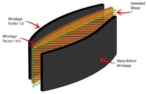
Back to our example. Whereas the starting point of our original mold was flat, the starting point for our windage mold is in the shape of an arc pushed 5.0 mm outward (see Figure 1). Depending on the stiffness of the material and the rest of the part’s geometry, that edge may only come back 2.5 mm toward flat. The reason for this is that an arch is inherently stiffer than a flat design, so it makes sense that it would not warp as much as it did for the non-windage mold.
So, how do you know what the starting point for a mold should be? You could make some guesses based on experience; however, because every part is different and so many different grades of resin exist, it will be difficult to get it right on your first guess.
Instead of guessing, we can use simulation. Using plastic injection molding simulation software, we first predict the warpage from the original design and then apply the windage factor by multiplying the negative of that warpage by some scale factor to each point on the model. We then re-run the simulation using the same conditions to see how close the warpage comes to being within tolerance. If it is still not within tolerance, we go back and keep reapplying a different windage factor to the design until we are satisfied with the results.
This methodology is basically the same as modifying the actual mold with one important distinction: With simulation, we cannot apply windage to just one section of the part without going back and modifying the original CAD data and re-creating the simulation model. So, we get as close as we can by applying the factor as described above. This significantly reduces the amount of time necessary to complete the windage analysis, although there is one drawback. Applying the negative of the predicted warpage times some scale factor will likely result in a shape that is not moldable due to undercuts, etc. However, an STL model of the best windage model can be exported and overlaid with the original CAD geometry, which can then be modified only in the critical areas. The final simulation model is created from this last CAD revision and run as a final check of the warpage predictions in those critical areas.
Simulation can be a tedious process, but it is a huge time- and money-saver compared to modifying the actual mold, not to mention that it can avoid the panic situations brought about by molding parts out of tolerance.
Putting into Practice
This methodology was tested recently for a project at Windsor, Ontario-based Build-A-Mold Ltd. Build-A-Mold needed to conduct simulation work on an automotive oil pan mold for which it had severe warpage concerns that were based on the company’s experiences with previous molds molded from similar glass-filled nylon materials.
Despite analysis efforts to improve gating, processing and cooling design, the best warpage that could be expected was nearly 15 mm around the part’s skirt profile. Compounding the problem was a predicted twist in the part, which meant that any windage being applied in simulation would be applied to the many ribs that ran the length of the part, essentially making undercuts.
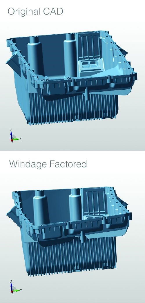
After several attempts, the right windage factor of 1.05 was determined to bring the warpage back to near-zero around the skirt. This was not like the aforementioned example where the windage factor came in lower than 1. The reason is that there was a tendency of this part to twist rather than bend in the shape of an arc. Next came the hard part—dealing with the ribs. A project engineer from Build-A-Mold’s trusted injection molding simulation provider handed off the STL model with the best windage factor to the Build-A-Mold engineering team, which then overlaid that model with its CAD model of the mold. From that overlay, the Build-A-Mold team conducted some intricate CAD surfacing work to produce a final 3D windage model of the mold with no undercuts (see Figure 2).
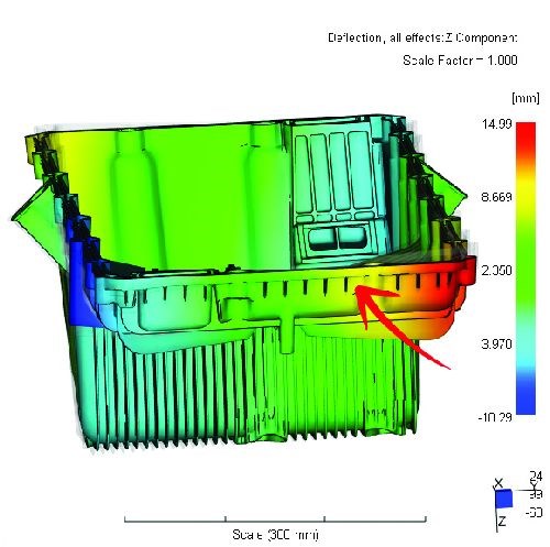
Some parts were then molded, and the resulting skirt flatness came within tolerance, although some adjustments still needed to be made to the inward/outward warpage of the skirt. In fact, it turned out that using a slightly different valve-gate sequence produced similar flatness results but better inward/outward warpage on the side walls, which was confirmed in simulation (see Figure 3).
From Build-A-Mold’s perspective, it was a bit of a leap of faith to trust the simulation results, because it had never before used them for windage. The results speak for themselves, however. Build-A-Mold estimates conservatively that it saved a minimum of $10,000 to $15,000 in tooling costs alone.
Summary
Applying Kentucky windage to a mold is not for the faint of heart. However, if a warpage problem cannot be solved through simulation to improve the mold design or process, then windage may be the last resort. If warpage simulation is conducted properly by experienced simulation engineers, it can be leveraged to take the guesswork out of windage, and reduce or even eliminate the tuning loops needed to bring parts into tolerance. Indeed, the sun shines bright on my Old Kentucky Windage.
Related Content
Three Good Reasons to Switch from Three- to Five-Axis Machining in Moldmaking
Five-axis machining technology is a great tool in the moldmaker toolbox.
Read MoreHow to Analyze and Optimize Cutting Conditions to Reduce Cycle Time
Plastic injection mold design and manufacturing company puts NC program optimization software module to the test. The results were surprising.
Read MoreIt Starts With the Part: A Plastic Part Checklist Ensures Good Mold Design
All successful mold build projects start with examining the part to be molded to ensure it is moldable and will meet the customers' production objectives.
Read MoreHow to Manage Wall Thickness Changes in Your Mold Design
To ensure even filling and cooling, consider wall section transitions, corners and fillets, ribs and bosses, lip and rim designs and CAE flow simulation software.
Read MoreRead Next
Get the Red Out
Using simulation to predict high-conductivity insert performance.
Read MoreHow to Use Strategic Planning Tools, Data to Manage the Human Side of Business
Q&A with Marion Wells, MMT EAB member and founder of Human Asset Management.
Read MoreReasons to Use Fiber Lasers for Mold Cleaning
Fiber lasers offer a simplicity, speed, control and portability, minimizing mold cleaning risks.
Read More
