The Designer's Edge: Flash Free Molding and Tool Deflection
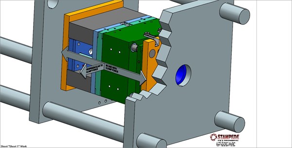
We presented the three conditions that make flash impossible. Today we'll look closer at the second condition, which involves the tool being robust enough to prevent deflection both in line with clamp force and perpendicular to clamp force.

My last post presented the three conditions that make flash impossible. Today we'll look closer at the second condition, which involves the tool being robust enough to prevent deflection.
An inadequate tool design can contribute to flash by allowing deflection in line with clamp force and perpendicular to clamp force. The tool must be designed to withstand the amount of cavity pressure it will see in both directions. I have been amazed over the years how plastics/cavity pressure can deflect the tool steel and the components.
When considering in line with clamp force, the area of focus is where the plastic is injected into the mold via runner systems and gates. This is typically where the highest amount of plastics pressure will be, and in many cases this is in the center of the mold (which is the weakest for deflection). This requires adequate support with pillars and rails on the ejector/core half (and the cover/cavity half, if hot runners and other mechanical actions are used).
I believe there is no such thing as “too much support,” as a lack of support can contribute to deflection. It's necessary to understand the importance of support pillars and the surface area of support they create (not just the number of supports or the designs based on a percentage of surface area between the rails).
Solely going from a one-inch to a two-inch support pillar, will yield 400 percent more surface area. Going from 2 inches to 3 inches will give you another 200 percent of surface area. Remember this: If the real estate allows it, you can never have too much support.
With support pillars, pre-load is part of the equation. However, there is not a standard spec that meets all scenarios. It comes down to the amount of support you have and the distance between the ejector rails.
For an exaggerated mental picture, consider this: If my rails were one inch apart, that’s one skinny ejector plate. I really wouldn't need support pillars or pre-load. But, if my rails were 36 inches apart I would need to design as much support as I could. And depending on the thickness of the mold, I may need to crown my pre-load--heaviest in the center and tapered down towards the rails.
The standards for pre-load are anywhere from .002 - .005. However, that is just a spec for the middle of the road. In some cases you won't need that much. In other cases, you may go as high as .015 crowned down towards the rails to prevent deflection. Again, the only reason excessive pre-load was needed was a lack of tool support.
In my next blog (February 20), we will dive into deflection perpendicular to clamp force.


