Simple Productivity Gains with Mold Design Automation
A look at where to find productivity gains within your mold design operations, as the complexity of components and materials used continues to increase.
The word automation means different things to different people, but when related to CAD/CAM there is a more common view. It means reducing menu clicks for frequent tasks. In a production environment, a frequent task could be something as simple as programming a certain type of groove on a turned profile. Saving these menu selections into a macro that could be used repeatedly would certainly save time.
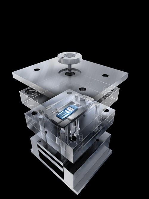
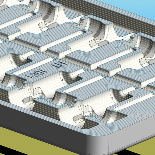
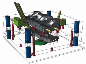
In relation to molds, throughout the last 20 years there has been much automation achieved in the improvements to CAD/CAM for mold design and machining. For instance, there are now many choices of CAD systems for the design of a mold, providing detail on its assembly and the passage of plastic into every feature contained in the cavity. On the CAM side, functionality such as pencil milling or rest machining can save hours compared to the guesswork of the past.
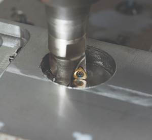
An often overlooked aspect of mold machining is the relatively simple task of machining the mold base and plates. Simple in that the geometry to be machined is not actually that complex—essentially holes of different sizes and purposes. However, while many companies will have invested heavily in 3-D machining software, some are still programming mold plates manually, either using a simple 2-D CAM system or plugging in locations on the CNC machine control. Neither is particularly productive, especially if you consider the tools available to automate the process. Location error is costly—either in terms of repair or the fact that they’re often not found until mold assembly begins.
The good news is that many molds are designed in 3-D with the output being some flavor of solid model that contains intelligent features, which define more than just the hole location. The feature will clearly show whether the hole is counter-sunk or threaded. Even if the feature cannot contain all the detail you wish to share about a hole, you can always apply a color to the feature that lets the machinist know something a little extra about the purpose of the hole. This information can then be used to automate the machining process.
In terms of CAM software, automation means macros, which are a package of processing logic that automatically generates instructions for machining a feature. The machining is optimized by the specific conditions and intelligence you decide upon. Automation processes can be as generic as machining a mold’s runner, sprue bushing and locating ring or sufficiently intelligent to machine ejector plates with d-headed pins, lifters and pry slots complete in one process.
Your manufacturing engineers and CAM programmers determine the automation processes, so the programmer no longer needs to dedicate time and attention to recognizing the appropriate machining information and manually creating machining cycles in the CAM software, which in turn frees up the programmer to focus on more complex projects.
The processes don’t have to be part specific. They can be developed for a family of parts or a general type of machining. For example, consider face milling. A standard set of machining logic consisting of climb milling at 0 degrees, appropriate face mill cutter selected based on the surface area of the base plate with a step over calculated as a percentage of the tool diameter and the depth-of-cut based on the tool’s recommended parameters. These parameters could then be applied to face milling operations on many different mold bases and components features. The basic automation logic is the same logic you would use to program the mold bases manually, but you are capturing them once and reusing them many times.
Parametric geometry plays a greater part for mold bases. Take for instance 3/8-16 UNC tapped holes in an ejector plate. The manual programming of selecting the proper tooling and the drilling cycle for tapped holes in an A, B, T or MUD base will not vary. When applying your automation process, the tapped hole features pass information to the process where decisions specify how the feature is machined. A tap drill is selected based on the feature’s diameter. Proper drilling cycle parameters are applied setting the clearance plane, retracts and hole depth, accordingly. These are the same decisions you would make if you program the job manually.
Logic can also be applied in the manufacturing process. For example, if the tapped holes are blind, set the cycle depth to the holes’ exact depth. If through, extend the hole depth by a factor (3 * tool dia) or by a specified amount (.100). Appropriate speeds and feeds are calculated based upon the material of the tool and the mold base being machined. The logic is all based upon your company’s proven manufacturing process.
Summary
Automation processes effectively apply your proven manufacturing methods consistently, maximizing your best practices and drastically reducing your programming time. The end result of automation is edit-free G Code and an error-free component. With the increasing complexity of components being molded and materials used, it is easy to lose sight of where some productivity gains can be achieved. Just remember, it’s not all 3-D.
Related Content
Hands-on Workshop Teaches Mold Maintenance Process
Intensive workshop teaches the process of mold maintenance to help put an end to the firefighting culture of many toolrooms.
Read MoreFundamentals of Designing the Optimal Cooling System
The right mold components can help improve mold cooling and thereby produce higher-quality parts.
Read More6 Ways to Optimize High-Feed Milling
High-feed milling can significantly outweigh potential reliability challenges. Consider these six strategies in order to make high-feed milling successful for your business.
Read MoreRead Next
A Specialized Mold Design Strategy
Solving complex mold design challenges with specialized CAD software.
Read MoreReasons to Use Fiber Lasers for Mold Cleaning
Fiber lasers offer a simplicity, speed, control and portability, minimizing mold cleaning risks.
Read MoreHow to Use Strategic Planning Tools, Data to Manage the Human Side of Business
Q&A with Marion Wells, MMT EAB member and founder of Human Asset Management.
Read More

