Modern Software Solutions in Measurement Metrology Improve Mold Build and Verification
Inspection and verification that the mold and the products it yields comply with the master CAD design are open to the benefits from modern development in CAD/CAM technology.
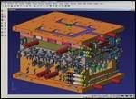
Mold builders and their customers have long applied themselves to the digital technology afforded by CAD and CAM. These technologies have been employed in design as well as manufacturing and include CNC machining, routing, EDM and other processes. But those aspects of the enterprise are not the only ones that are open to great benefits from modern developments in CAD/CAM technology. So too are the processes of build and inspection, verification that the mold and the products it yields comply with the master CAD design. This is done by coupling modern model-based measurement metrology software with 3-D digital devices including portable or fixed CMMs (coordinate measuring machines) or other 3-D equipment.
Model Based Definition
Model based definition (MBD) is not a new idea. However, full fruition of the concept has eluded manufacturing since its inception. Generally speaking, the goal of MBD is to eliminate drawings and other outdated elements of product definition in order to lean processes and reduce discrepancies. The list of benefits from MBD is a long one. Some of the key benefits are eliminating the cost of drawings, putting an end to discrepancies between the drawing and the CAD model, and speeding up the design and build process. By having a fully digital collaboration medium, there are endless efficiencies available to the enterprise—including a company’s vendors and customers.
Modern measurement metrology solutions allow MBD to be applied to the entire product lifecycle. In recent years, digital measuring technology has made great advancements including considerable improvements in portable CMM-type devices. This has helped make the technology more accessible to more companies and to more elements within a company. Now the full potential of these advances is being realized thanks to developments in model-based software solutions.
Inspection/Verification in Minutes, Not Hours or Days
Thankfully these days a CAD model of the part and tooling almost always exist. The CAD model can be used directly in many CMM packages for inspection on programmable CMMs. More immediate results are possible using real-time solutions that allow on-the-spot decisions.
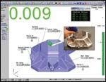
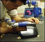
Modern measuring software used live with a CMM device, such as an articulated arm, takes advantage of the availability of the model as the product’s master digital definition. A user imports the CAD model into the metrology software, aligns the inspection article to the device and to the CAD model with a quick and simple routine, and then instantly begins getting information on the part’s accuracy. This “virtual gage” tells where the part is out of tolerance and gives manufacturing immediate information on where and how much the part needs correction.
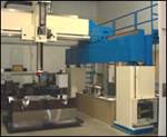
Older methods take hours or days to get these kinds of answers. Non-CAD based methods are slower and create numerous opportunities for error and ambiguities. For parts that have contour or complex shapes, CAD-based inspection is the only practical solution. Older techniques offer little more than x, y, z coordinate values along with the associated deviations. CAD-based solutions with a hard probed device give instant, real-time information. High and low spots on the part can be readily seen and assessed, and deviations are clear and obvious—eliminating the guessing game. For multi-part assemblies such as molds, CAD-based live inspection will remove doubt as to which part(s) are in spec and which ones are out.
Digital Build and Assembly
In addition to simply identifying where the part or tool is out of specification, the CAD-based metrology solution also allows digital computer-aided manufacture and assembly. Again using the CAD model, a user can place a probe alongside a feature on the part, and with live on-screen indicators place components, features, holes, etc., exactly where they belong as directed by the CAD model. Also, powerful metrology software allows manufacturers such as thermoformers and sheet metal manufacturers the ability to check and create scribe lines for EOP (edge of part) trim.
Reverse Engineering: Quick Capture of the As-Built Condition
Often moldmakers seek new business that involves parts that have no CAD model, and modern manufacturing processes require one. Creating a model from a part or tool, referred to as reverse engineering, is made easier and faster using a CAD-based metrology software package.
Again connected to a real-time digital device, the user takes organized data with a hard probe, creating CAD entities in real time. Hard probes allow “scanning” a stream of points, which is not possible with a touch probe. Primitive shapes such as planes, cones, cylinders and spheres are measured automatically creating CAD geometry as they are measured. More important are complex geometries and curved surfaces.
The more powerful CAD-based software packages have tools to take scanned data from a hard probe or non-contact device—such as a laser scanner—and create accurate smooth surfaces. Built-in solid modeling also is important to speed and simplify the real-time reverse engineering process. With solids, users can extrude, trim, fillet, core-out, etc. All of this is made easier if done in real time versus giving vast amounts of data to engineering and hoping they can make something out of it all.
Selecting a Modern and Productive Software Solution
There are numerous software solu-tions available for real-time, CAD-based measuring metrology. Each one has strengths and shortfalls that distinguish them from the others. Key aspects to consider when looking for the best solution are:
- Ability to read, organize and work with CAD models accurately and easily. Many systems are based on proprietary viewers. These may struggle with larger CAD models, are subject to reversing surface normals, missing surfaces, and have little or no way to fix problems or make needed adjustments to models. CAD-based systems are built upon robust, proven CAD/CAM platforms that do a better job of handling models and bringing them in organized on layers/levels and colors of the original model.
- Able to read native CAD models. Most systems require neutral formats such as IGES and/or STEP. A more versatile and enterprise friendly system can read native models such as Catia, Solidworks, Unigraphics, Pro-Engineer, etc.
- True, real-time operation. Older technology only allows the operator to take data and then later produce a result. Newer systems are live, giving instant “virtual gage” operation.
- Modern alignment techniques. All metrology systems have some method of aligning the CAD model with the device and the part. But many use old limited techniques that are difficult, slow and are not saved as part of a fixed inspection routine. Newer methods involve automated alignment tools that are easy to create, easy to learn, and are saved in the model so that each ensuing alignment is done quickly and the same way every time.
- Robust, customizable reporting. Im-portant is the ability to customize reports, display and print graphical color maps, and compatibility with widely used business software such as Microsoft Excel.
- Best-fit with control over six axes. In order to utilize the full range of tolerance available, best-fit allows the data set to be shifted relative to the model using proven, accurate algorithms. This can save a part that would otherwise be scrapped.
- Full support of MBD. The software needs to offer the ability to set unique tolerances, datum constraints and entity IDs in the model. Modern systems are able to read these elements directly from the native model.
- Compatibility with a broad spectrum of measurement device types and manufacturers, allowing a common metrology platform within the enterprise.
Companies are quickly recognizing the considerable productivity advancements and lean techniques provided by model-based manufacturing and inspection. They also are finding that these methods are vast improvements in collaboration and process control throughout the entire enterprise. Furthermore, it is difficult to ignore the fact that major manufacturers are demanding that their partners utilize these modern processes as part of their digital product definition strategy.
Related Content
How to Solve Hot Runner Challenges When Molding with Bioresins
A review of the considerations and adaptations required to design hot runners and implement highly productive injection molding operations.
Read MoreMMT Chats: Eliminating the Noise to Stay Focused on the Customer
Metro Mold & Design joins me to discuss the value of the 80/20 rule as a business strategy, its talented cross-functional team, the role of automation in mold building and molding, and the continuing impact of COVID-19.
Read MoreHow to Use Scientific Maintenance for More Accurate Mold and Part Troubleshooting
Discover how adopting scientific maintenance approaches helps improve mold lifespan, minimize failures, and optimize production outcomes.
Read MoreConfronting the Mold Design Talent Drought
Recently, I reposted on LinkedIn the results of an informal survey we conducted, which revealed a shortage of skilled mold designers. It quickly gained a lot of traction. Given the response, I thought I'd summarize the feedback and keep the conversation going.
Read MoreRead Next
Streamlining Processes with The Right CAD/CAM Package
VISI-Series provides the toolmaker a high level of productivity through its specialized applications, and offers dedicated solutions while eliminating the links between varying software suppliers and the solid-to-surface geometry conversions required by traditional systems.
Read MoreThe Benefits of a Remanufactured CMM in Your Shop
The only way to economically meet the need for a large gantry CMM with an uncommon measuring envelope was to find an existing one, rebuild it and remanufacture it.
Read MoreHow to Use Continuing Education to Remain Competitive in Moldmaking
Continued training helps moldmakers make tooling decisions and properly use the latest cutting tool to efficiently machine high-quality molds.
Read More
