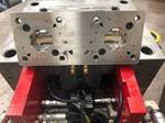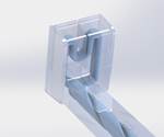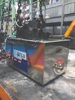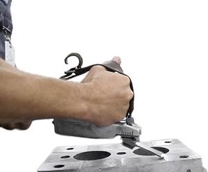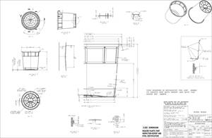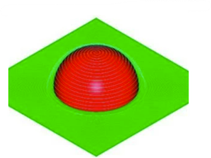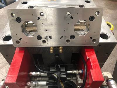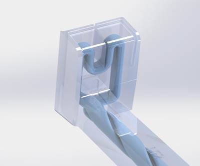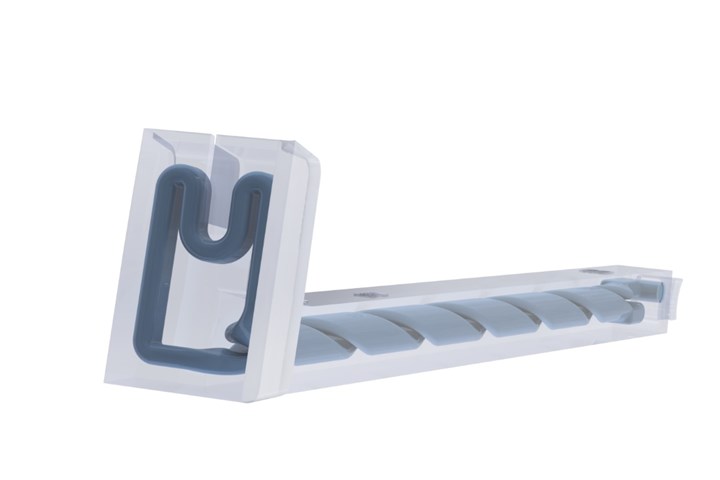
Figure 1. A consistently-spaced cooling circuit to the surface of the mold is the key to success in conformal cooling. Images courtesy of Next Chapter Manufacturing.
Additive tooling refers to the use of 3D printing (e.g. direct metal laser sintering or DMLS) to produce mold inserts out of metal, specifically tool steels, that will be used to produce high-volume class 101 molds. Additive tooling also includes sub-inserts that will go into larger molds or mold bases, slides, lifters, gate inserts and eventually complete mold plate cavities that form the plastic. Additive tooling differentiates the tooling between high-volume, durable class 101 tooling and simple, 3D-printed resin tools for prototyping.
At the core of designing for additive tooling is thinking in the reverse of mold construction. For example, many common CAD modeling features are designed around milling and drilling, so the traditional mold build begins with a billet of steel, from which the required material is cut away to reach the net shape. When you think in the reverse, you actually add material to make the shape of the tooling required to produce parts from the mold.
This shift in thinking will transform how shops design molds, route cooling circuits, provide clearance and finish machine, streamlining the workflow from design through mold construction.
Get Creative with Cooling Design
Conformal cooling is prevalent in moldmaking. A primary driver of conformal cooling is the ability of a cooling circuit to follow the contour of the plastic molding cavity surface, yielding consistent cooling. Another driver is getting water into places that conventional milling and drilling will not allow. However, both benefits require creativity when it comes to creating complex contours, avoiding dead spots and promoting turbulent flow.
Conformal cooling also remains the top application of additive manufacturing in moldmaking—conformally-cooled 3D-printed mold inserts or additive tooling. Many mold builders have adopted additive tooling to differentiate their mold performance from the competition, but many designers hold onto the subtractive mindset, so the cooling circuits still look very conventional despite eliminating cross-drilled waterline plugs. Here is where additive tooling shines, as it enables limitless design constraints. However, conformal cooling is a delicate balance of creativity and convention. Conventional mold design standards are still important for maintaining design discipline to create highly-efficient cooling circuits.
For example, to maintain consistent cooling across the mold surface, keep cooling circuits consistently spaced apart. It is important to note that cold spots are possible in a mold, which, just like hot spots, can negatively impact molding performance. Consistency is key (see Figure 1).
Things start to get interesting when working with circuit profiles because numerous options are available to promote more surface area and turbulent flow. Some profiles have internal grooves to maximize surface area while others have spiraling ramps that promote turbulent flow.
Most of these designs do not consider the build process and create features requiring supports that can restrict the cooling circuit flow or create sharp corners where concentrated stress could cause cracking. Elliptical or elongated cooling circuits are the best option for maximizing flow, achieving optimal thermal transfer and squeezing in between narrow steel sections that need the most cooling (Figure 2).
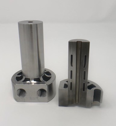
Figure 2. Elongated circuits maximize surface area while being simple to build in the additive process.
A controversial cooling circuit design is splitting circuits into several smaller channels and feeding them with a larger circuit from the mold. For example, a great way to minimize the number of circuits in a mold is to use a large inlet (¼-inch or ⅜-inch NPT waterline) that you break off into multiple waterlines and then rejoin at the exit.
However, with this design a circuit can get blocked and go undiscovered until the molder is producing bad parts. When you use a single circuit, you can easily monitor the in-and-out for flow and quickly identify any issues.
Another consideration when using multiple lines is the DMLS powder getting in the lines after a build. Multiple lines make it difficult to determine if all the powder evacuates prior to heat treatment. If the powder gets stuck in the circuit, shops must then scrap the insert. You can mitigate the risk of splitting waterlines internally by limiting the split section to less than one-third of the overall circuit length. This rule of thumb helps to maintain the larger flow and then splits the circuit only in the critical location required, enabling the powder to evacuate without the risk of a blockage.
Once you have an optimal circuit design, conduct a cooling simulation study to confirm effectiveness and then run FEA analysis to confirm the insert’s integrity and sufficient steel conditions for injection pressures. Taking this approach to circuit design identifies the most appropriate solution for the mold design before building the inserts.
Maximize Clearance to Minimize Machining
Using an additive mindset helps to determine exactly what is needed to form the part shape detail while eliminating material in the rest of the insert, reducing cost and avoiding secondary machining. However, while most 3D printing processes produce surface properties adequate for cooling channels, they do not produce the necessary surface finishes or tolerances to eliminate precision machining. To combat this limitation, add machining stock to the CAD model and build the part oversize to finish machine the part to precision tolerances.
Moldmakers commonly add clearance between two pieces of steel to minimize wear, improve venting, reduce thermal transfer or aid in-mold assembly and disassembly. You can achieve each of these benefits with additive tooling by 3D printing complex clearances instead of conventional milling or drilling.
For example, a core or cavity insert in a mold base relieved on the mating surfaces by about 60%. Building the insert additively and then finish machining the remaining 40% of mating surfaces will reduce machining time and cutting tool wear (Figure 3).
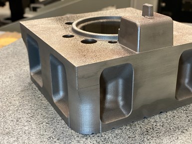
Figure 3. Additive mold insert designed with relief to minimize finish machining and mold assembly.
Adding the machining stock to the part shape only requires finish machining or EDMing the cavity surface, which eliminates roughing, stress relieving, EDM hole drilling and roughing electrodes. This approach yields a 50% reduction in electrode machining and burning time compared to conventional machining from billet.
Simplifies Additive Tooling Workflow with Software
Software plays a significant role in simplifying or automating mold design and manufacturing. Additive tooling is no different in that there is a significant amount of time that goes into designing cooling circuits into impossible-to-cool areas. Today’s software tools for additive manufacturing like Netfabb and nTop offer dedicated conformal cooling design functions that simplify the design process and reduce circuit design time. This streamlined process moves the design to simulation faster, confirming effectiveness before 3D printing the inserts.
Today’s additive software provides the confidence to build additive tooling with success by checking build printability, automating support structures and simulating the build to identify potential stress or distortion areas and optimize as needed.
Related Content
The Benefits of Hand Scraping
Accuracy and flatness are two benefits of hand scraping that help improve machine loop stiffness, workpiece surface finish and component geometry.
Read MoreIt Starts With the Part: A Plastic Part Checklist Ensures Good Mold Design
All successful mold build projects start with examining the part to be molded to ensure it is moldable and will meet the customers' production objectives.
Read MoreMaintaining a Wire EDM Machine
To achieve the ultimate capability and level of productivity from your wire EDM on a consistent, repeatable and reliable basis, regular maintenance is a required task.
Read MoreRead Next
Additive Tooling Goes Beyond Conformally Cooled Inserts to Simplify the Mold Build Process
Three ways that additive tooling is moving past conformal cooling to bring speed and efficiency to the overall tooling process.
Read MoreSelling the Value of Additive Tooling in a Mold
Gaining molder buy-in for a conformal-cooled mold insert requires communicating the mold’s total cost of ownership over the life of the project.
Read MoreHow to Maintain Additive Tooling
Implementing additive tooling into a mold can be a daunting task, but maintaining it over the life of the tool can be straight-up scary. Here are three steps to include in your maintenance plan.
Read More

