Engineering the Micro
Here’s a look at just a few notable design features of the Kern Micro, the machine tool builder’s latest offering and the subject of many of the demonstrations at its recent open house in Germany.
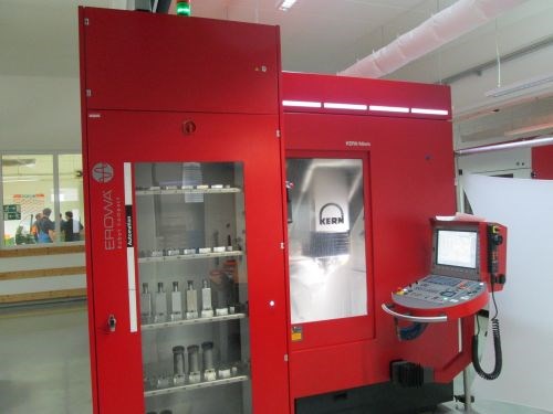
The Kern Micro in this shot, taken at the company’s contract manufacturing operation in Murnau, is set up with an Erowa robot compact for a particularly challenging application: completely unattended production of customer parts made from material that’s 23-percent cobalt.
Featuring multiple technical demonstrations, presentations from customers, and tours of two separate facilities, Kern Microtechnik’s April 23-24 “Precision Days” open house packed a lot of information into two short days in Southern Germany. The stars of all these proceedings, of course, were the machines themselves—machines with a number of design characteristics that struck me as a bit unusual. (Notably, the company’s technology development is heavily informed by real-world applications).
That’s particularly true of the company’s latest offering, the Kern Micro, which is also the machine with perhaps the broadest appeal for U.S. mold manufacturers. Capable of running with water-based coolants, oil mist or completely dry, the machine is said to be well-suited for cutting both steel and graphite electrodes (vacuum systems and other options are available for the latter). Like all Kern machines, it’s designed for nano-level precision (According to the company, positional tolerances of +/-0.5 µm enable achieving part accuracy to +/- 2 µm.) Meanwhile, a high-capacity toolchanger, workpiece palletization and both three- and five-axis configurations ensure plenty of options. Here are just a few of the ways Kern has achieved its goals for precision and versatility with this particular model:
Automated workpiece handling. Like many other models on the market, the left side of the machine’s workzone is open to accommodate a robot. However, workpiece handling doesn’t have to be limited to external systems. It can actually be built into the toolchanger.
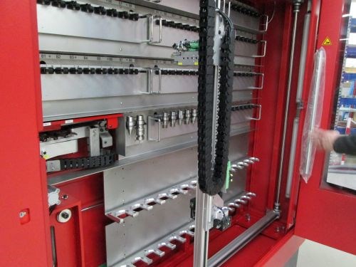
The upper stations are for tools; the lower stations are for workpieces.
Rather than the carousel common to many other machine designs, that toolchanger incorporates rows of cutters that are retrieved and brought to the workzone by a pneumatic arm. Total capacity is 209 tools, but customers have the option of sacrificing 90 of those slots to instead accommodate as many as 30 workpieces instead (maximum part size for these 30 stations is 75 × 75 × 150 mm). After all, for the pneumatic arm, retrieving raw material is essentially no different from retrieving cutting tools. With no additional software, components or training required, this configuration adds versatility without adding to costs or floorspace requirements (although some customers opt for both this option and an external robot). However, it’s only available with the machine’s five-axis configuration because the table has to tilt 90 degrees to interface with the pneumatic arm.
Flexible tool selection. The Micro’s toolchanger is also notable in that the rows of cutters are sub-divided into separate, quick-change pallets with 8 stations each. This enables operators to store complete sets of tools for any given job or application separately and retrieve them as-needed to minimize setup time. So long as the program doesn’t call for a tool in the pallet being swapped, this task can be performed while the machine runs.
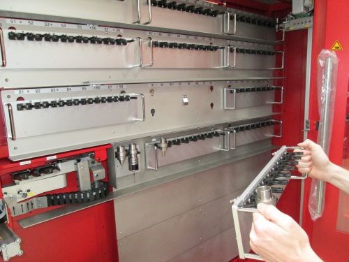
Removable toolchanger pallets add to the machine’s flexibility.
Aluminum Axis Construction. That’s right: the axes of the Kern Micro aren’t made of steel. They’re 100-percent aluminum. This construction is said to enable smoother machining because aluminum is both stiffer and lighter than steel. That said, aluminum also has a higher thermal expansion coefficient, so making this design work required an intensive focus on temperature control.
Intelligent temperature management. All machine components, including the aforementioned aluminum axis structure, the spindle, the electrical cabinet and coolants, are kept at a constant temperature of 20°C (which can be raised or lowered as desired). In essence, the company’s patented temperature management system relies on dissipating heat by pumping cold water through critical areas of the machine and the entire periphery.
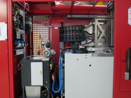
A look at the machine’s internals reveals no chiller within the enclosure. This configuration eliminates a common source of heat, which can adversely affect machining accuracy.
Two aspects of this system struck me as particularly unusual. First, a look inside the machine reveals no obvious mechanism to chill the aforementioned water. That’s because chillers produce heat—heat that would otherwise radiate throughout the machine and even into the wider shop. Given the potential effect of this heat on machining accuracy, the company opted instead to employ a system relying on an external chiller, a water-to-water heat exchanger and two, independent cooling circuits. Cold water pumped into the machine on one circuit absorbs the heat of warm water on its way out of the machine on the other circuit (thus, only heat is exchanged, not water). The result is a constant, stable temperature. And with the chiller located outside the machine enclosure, any excess heat it creates can be pumped away from the machining environment or used to heat the facility.
The second aspect of the system that caught my eye is the fact that the temperature control system doesn’t stop with the machine. It also extends to the workpiece. Underneath the table is a system that employs both water (for cooling) and oil (for heating) to keep parts at a constant temperature.
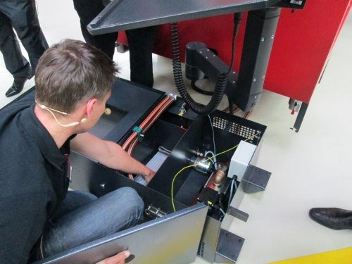
Matthias Fritz, head of product development and primary designer of the Micro, shows attendees the workpiece cooling system located beneath the workzone.
According to the company, this temperature control system is responsible for much of the machine’s nano-level precision. To demonstrate that precision, Kern conducted a “step test” that involved machining three separate faces from a bar inserted into the collet chuck on a five-axis Micro.
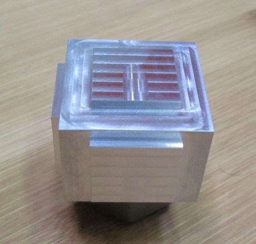
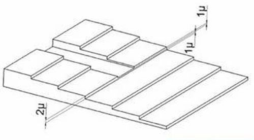
First, the machine cut five “steps” into one face, leaving a height difference of exactly 2µm between each. Next, it cut a slot, visible on the top face running perpendicular to the steps, to a depth of 5 µm when measured from the top of the block. Measured from the second step down, the groove is 3 µm-deep. From the third step, the depth is 1µm. Thus, the floor of the groove is also exactly 1 µm higher than the top of the fourth step, which the cutting tool didn’t touch. The machine then repeated these operations on two more adjacent faces, first by indexing the table 90 degrees and then by tilting it 90 degrees. (Diagram below courtesy of U.K.-based Kern supplier Rainford Precision).
For specifications and other information on the Micro, visit Kern’s website, where you’ll also find overviews of the company’s other equipment.
Read Next
Reasons to Use Fiber Lasers for Mold Cleaning
Fiber lasers offer a simplicity, speed, control and portability, minimizing mold cleaning risks.
Read MoreAre You a Moldmaker Considering 3D Printing? Consider the 3D Printing Workshop at NPE2024
Presentations will cover 3D printing for mold tooling, material innovation, product development, bridge production and full-scale, high-volume additive manufacturing.
Read MoreHow to Use Strategic Planning Tools, Data to Manage the Human Side of Business
Q&A with Marion Wells, MMT EAB member and founder of Human Asset Management.
Read More


