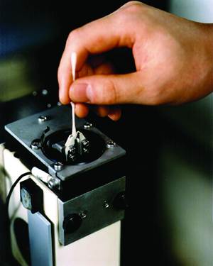
More moldmakers are using contemporary five-axis CAM software today, which has greatly reduced the need for die sinking EDM requirements. But, the software has not completely eliminated the requirement for electrode design and manufacturing.
Certain geometrical features like deep slots or small internal corner radii are not easily milled using available software and tooling. These geometries require electrodes that are manufactured out of materials such as graphite or beryllium copper alloys, which are machined on traditional three-axis or five-axis machines. The electrode is electrically charged and the geometry of the electrode is burned into the core or the cavity by way of the spark, which is generated upon contact. All of this is done while the part is submerged in an oil bath that helps to conduct the electricity and flush away particles from the eroded pattern.
Historically, electrode design and manufacturing were time-consuming and counterproductive processes, requiring the designer to manually identify non-machinable areas. The surfaces comprising those areas would then need to be copied, tangentially extended to a common Z height, linearly extended for clearance and trimmed to the electrode profile. Generally, it was not until the entire electrode was designed before the programmer even got a chance to look at its manufacturing requirements.
Streamlining Electrode Design
Today, moldmakers can take advantage of advanced CAD/CAM software that includes dedicated electrode design capabilities. These capabilities greatly reduce the time required for designing, modeling and manufacturing electrodes. With these systems, one person can be responsible for both the electrode design and manufacturing, which eliminates the need to go back and forth between CAD and CAM software.
With advanced CAD/CAM software that includes dedicated electrode design capabilities, one person can be responsible for both the electrode design and manufacturing, eliminating the need to go back and forth between CAD and CAM software.
The design of advanced CAD/CAM software includes modules that were created specifically for core and cavity model analysis and the automated generation of full EDM requirements such as the electrode model and documentation. Electrode models that electrode designers and programmers generate are automatically color coded, which further eases manufacturing. Documentation is also generated, including individual electrode drawings with full manufacturing notes and assembly drawings that show every electrode with their respective X, Y and Z locations and any C rotation.
Advanced CAD also performs system analysis to isolate and identify potential electrode requirements. The CAD software analyzes the part based on an established coordinate system, and it displays the results using pre-set parameters, designating a minimum radius or minimum draft angle. A color-coded display of the core or cavity identifies areas fitting the required parameters. Some CAD systems will even create curves identifying those areas, further streamlining the manual identification of electrode requirements.
Prior to creating the electrode, the electrode designer or the programmer should ensure that the CAD system establishes a new EDM coordinate system, because the NC coordinate system for EDM work is often different than the NC coordinate system for core or cavity machining. For optimal results, the CAD system should automatically identify intelligent EDM coordinate systems, which are then established with the simple selection of a displayed point. The new coordinate system is used for machining the electrode, generating detailed drawings and posting out machine instructions to the sinker EDM machine.
Next, the electrode design user interface can be used to define electrode requirements. The interface should be intuitive and simple-to-use, following logical, easy to understand steps. Also important is using CAD software that offers an electrode section suitable for both solid and surfaced models.
The CAD system should offer several selection methods to easily include only the geometry that is necessary for electrode development, including by color, layer, two-point box selection, tangent surfaces or even by chaining the boundary of the area using the actual surface edges. The CAD system should then automatically fill any holes within the selected geometry.
The CAD system should offer several selection methods to easily include only the geometry that is necessary for electrode development, including by color, layer, two-point box selection, tangent surfaces or even by chaining the boundary of the area using the actual surface edges. The CAD system should then automatically fill any holes within the selected geometry.
Ideally, within the same interface, the electrode designer or programmer will have parameter settings to establish common electrode properties, such as the length of the tangential and linear extensions as well as the electrode coordinate system and spark gap locations. Additionally, the software should provide an area to select the finished electrode’s color scheme. The electrode designer or programmer can use the colors (erosion surfaces, tangential extensions, linear extensions and so on) at a later point for a more automated manufacturing process, because the parameters do not require adjustment for each electrode once the designer or programmer enters them.
Once the electrode designer or programmer selects the electrode geometry, the software creates and displays a fully developed electrode. The electrode should include the geometry that is necessary for machining the electrode, a fully modeled holder and an electrode blank, all ready to be used as a stock model for electrode manufacturing. CAD systems that are intelligent enough to select the blank and holder from a library based on a best-fit scenario are the most productive.
Documentation generation should be automatic, but flexible, displaying pertinent data in the title block. Pertinent data includes items like electrode material, number of electrodes required from rough to finish, spark gap and orbit style.
Integrating CAD and CAM
CAD-based electrode design software that is directly integrated with CAM software that uses a single database, such as hyperCAD-S, eases automated electrode manufacturing. It enables full integration between the electrode model and the manufacturing process. This means that parameters such as electrode material, spark gap, blank size, positional reference (including automated C-angle orientation to minimize blank size) and automatic coloring of the various electrode components (erosion surfaces, tangential extensions, linear extensions and so on) are merged into the CAM software. At this point, the programmer can select macros that apply various toolpaths to the designed electrode. These macros, or collections of toolpaths, should identify the material being machined (based on color) and the general size of the blank and spark gap as input during electrode design. These parameters are then used to adjust the various toolpaths to achieve the desired results.
Once all electrodes are manufactured, the CAD/CAM system can export the actual machine code that is required for the operation of the sinker EDM machine. The output includes the electrode numbers and the X, Y and Z positions, including any C-rotation and machine parameter settings. This eliminates all-too-common errors that result from users entering the information manually.
A process that previously required hours to complete now requires only a few minutes. Using sophisticated electrode design and manufacturing software, the time-intensive process of electrode development and machining can be a point and click away.
A process that previously required hours to complete now requires only a few minutes.
About the Contributors
Alan Levine is the managing director, and Alan Zielinski is senior application engineer of Open Mind Technologies USA.
Related Content
Maintaining a Wire EDM Machine
To achieve the ultimate capability and level of productivity from your wire EDM on a consistent, repeatable and reliable basis, regular maintenance is a required task.
Read MoreHow to Improve Your Current Efficiency Rate
An alternative approach to taking on more EDM-intensive work when technology and personnel investment is not an option.
Read MoreBuilding Molds: Most Popular Reads of 2024
Dive into the most-viewed content for building your mold, including topics such as cutting tools, EDM, hot runners, additive manufacturing, mold materials, machining and mold components.
Read MoreIntegrated CAD/CAM Streamlines Electrode Manufacture, Improves Quality
A focus on electrode design and automation helps toolroom improve efficiency, reduce tooling costs and deliver higher quality products.
Read MoreRead Next
How MoldMaking Technology Magazine Came to Be
Twenty years ago a moldmaker launched this magazine, legitimizing an industry and then passed it on to a passionate media company, which took it to the next level.
Read MoreHow to Use Strategic Planning Tools, Data to Manage the Human Side of Business
Q&A with Marion Wells, MMT EAB member and founder of Human Asset Management.
Read MoreReasons to Use Fiber Lasers for Mold Cleaning
Fiber lasers offer a simplicity, speed, control and portability, minimizing mold cleaning risks.
Read More


