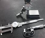
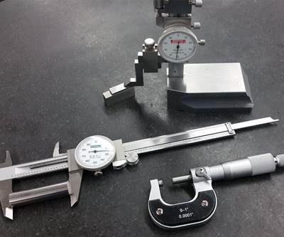
Mold builders who produce the highest quality molds should use the best quality control practices, as the quality of a mold is only as good as the accuracy and reliability of measurements.
A mold builder can avoid difficult gaging situations by enforcing strict quality control processes, which ensure gages are properly calibrated to international standards of measurement and employ proper care and maintenance procedures to maintain accuracy.
This approach to measurement and inspection will ultimately lead to consistent, reliable gaging results and improve mold quality.
Defining Measurement
The British yard and meter, as defined by the Weights and Measures Act of 1878, are the two units of measurement most common in the United States. These practical measurements are defined as the international inch in terms of light waves.
The meter is the basis of all measuring systems with the international inch defined as 25.4 mm exactly. Over the years, the meter has been defined in different ways. Currently, the meter equals the distance light travels in a vacuum during 30.663318 cycles of a Cesium atom. Of course, this cannot be used for regular measurement, so the physical relationship is translated by the National Institute of Standards and Technology (NIST) using lasers and atomic clocks and transferred to today’s most basic and accurate precision standard: gage blocks. Gage blocks are the standards that bring this technology to the shop floor where different sizes of blocks may be combined to give any required dimension.
This approach to measurement and inspection will ultimately lead to consistent, reliable gaging results and improve mold quality.
Assessing Gage Blocks
Precision gage blocks are the primary standard for dimensional quality control in the manufacture of interchangeable parts. These blocks are used for calibrating precision measuring tools and for setting numerous comparative type gages used in incoming, production and final inspection areas. Gage blocks provide the most economical, accurate method of setting dial test indicators and other gages used in conjunction with surface plates for inspecting workpieces with exacting tolerances.
Essentially, gage blocks consist of hard, stable material with a flat, parallel gaging surface on each end. The measuring surfaces are ground and lapped to an overall dimension with a tolerance of plus or minus a few millionths of an inch. Gage blocks may be stacked or “wrung” together to form accurate standards of any practical length, limited by assembly and handling of the wrung together blocks.
Gage blocks come in several grades or degrees of accuracy. Grade 0 is the most popular grade, as it is usually suitable for most applications and offers the best combination of accuracy and cost. Higher accuracy grades of blocks, such as Grade 00 are primarily used as masters to check other gage blocks and for applications that require extreme accuracy. Grade B (±50 microinches) blocks are relatively inexpensive but are limited to workshop use, where exacting accuracy is not required.
Gage blocks are available in various materials, such as chromium carbide,* which is long-wearing, dimensionally stable and extremely corrosion resistant. Gage blocks of this material will maintain their accuracy many times longer than steel blocks and are available in ASME B89 Grades 00 and 0.
Another material option is ceramic, yielding long-wear and corrosion resistance. Ceramic gage blocks fill in the gap between steel and chromium carbide and are available in Grades 00 and 0. These blocks have favorable mechanical and thermal properties that compare the closest to steel of any alternative gage block material.
Steel is the most economical gage block material available, and steel’s thermal and mechanical properties are adequate in typical workshop environments. The main disadvantage of steel is its susceptibility to corrosion.
Various styles of gage blocks are available, including rectangular, square and heavy-duty. Certain accessories can extend the use of gage blocks such as height gages, snap gages, scribers and dividers.
Gage blocks are the standards that bring this technology to the shop floor where different sizes of blocks may be combined to give any required dimension.
Ensuring Even Work Surfaces
Every linear measurement depends on an accurate reference surface from which the user takes final dimensions. Precision granite surface plates provide the best reference plane for work inspection and layout before machining. They are also ideal bases for making height measurements and gaging surfaces, parallelism, etc. A high degree of flatness, stability, overall quality and workmanship also make them an appropriate choice for mounting sophisticated mechanical, electronic and optical gaging systems.
The percentage of quartz in the stone is the most important element for the performance and life of a granite surface plate. Quartz is more than twice as resistant to wear as the other minerals in granite. It provides bearing points that are of a hard, highly polished, smooth character that protects the accuracy and finish of both the surface plate and the tools and instruments used on it.
Use surface plates without work clamping ledges for sustained accuracy and reliability. Ledges are for work clamping purposes only. If you use excessive torque when applying clamps to ledges, it can adversely affect measurements taken near the plate edges. If clamping is important, install T-slots and threaded metal inserts on the surface.
Some applications may warrant customized, special plates. For example, you might need a custom-made plate for inspecting oversized workpieces, such as a complex mold. Or a special plate or modification to a standard plate might be required for workholding attachments such as threaded inserts, studs, adaptor holes, T-slots and dovetails, etc.
Granite surface plates come in three grades of accuracy:
- AA: Laboratory grade for precision operations in constant temperature gaging rooms and metrology departments.
- A: Inspection grade for general work in quality control.
- B: Toolroom grade for production checking work throughout the shop.
All surface plates must pass a critical final inspection to prove that their surfaces are within the specified tolerance. The final inspection is typically done with an autocollimator in a controlled atmosphere. This instrument is checked and certified against standards traceable to NIST.
Taking Good Care
To properly care for gage blocks, use wringability to evaluate the integrity of the gage block’s surface condition. Wringability is the ability of two surfaces to adhere tightly to each other in the absence of external means, which is an important property of gage blocks. Blocks that don’t wring may give erratic and unreliable results and should be replaced.
To prepare gage blocks for wringing, free blocks from nicks and burrs because imperfections on one block may damage the surface of another block. Check blocks for defects with a gage block stone before wringing. Use a stone with serrated grooves because it gives a better “feel” for nicks and burrs that catch the edges of the serrations.
If stoning is required, this process will remove a small amount of raised material, improving the repeatability of readings and providing block sizes that appear to be truer to their original tolerances. Ultimately, blocks that are free of defects will wring together better.
To wring gage blocks, clean all surfaces. Use an oiled wring pad to wipe the surfaces of the blocks. Next, use a dry pad to remove as much oil as possible. The blocks should then slide together without any feel or bumps or scratching and should adhere to each other strongly after being rotated into place.
If you suspect a problem with a block, use a formal wringability test that does not require a laboratory to perform. Wringability is an important gage block property but is, fortunately, a quality that can be controlled and monitored readily by the user of the blocks. With proper use and care, quality gage blocks will provide long, reliable, accurate service.
Gage blocks provide the most economical, accurate method of setting dial test indicators and other gages used in conjunction with surface plates for inspecting workpieces with exacting tolerances.
The granite surface plate is a precision piece of equipment that requires proper installation and maintenance. Before use, furnish the plate with a reliable support system. Typically, this is a hard rubber pad attached to the bottom of the plate forming a non-distortable three-point support system. The pads are installed during manufacturing, and the plate rests on them throughout lapping, inspection and shipping. They are a critical factor in surface plate accuracy, so do not remove them.
Furnish plates up to and including 6 feet wide by 12 feet long with a non-distortable three-point support system. When mounting the plate on a stand, be sure only the pads are resting on the stand. Never support the plate by the ledges or under its four corners, as this will completely void guarantee of accuracy.
Support larger plates on multiple support points (six or more points) with granite pedestals and leveling wedges. Plate size determines the number of support points and proper positioning. Plate thickness and overall working height determine the height of the granite pedestals. Use nylon slings when lifting the granite, and if a forklift is required to move the granite surface plate, place protective padding between the metal forks and the granite.
Once set up, plates do not require extensive care and maintenance. Keeping the surface clean and free from buildup of dust, dirt, grease, grime and other foreign particles will maintain accurate tool readings and extend plate life. Environment and usage determine cleaning frequency. However, as a rule, clean a plate daily if you use it every day. If you do not use the plate for an extended period of time, use a surface plate cover.
Check surface plates regularly for wear using a repeat reading gage with a manual indicator.
Take care when using granite surface plates. Do not treat them as workbenches or lunch tables, do not drop wrenches or hammers on plates that will chip and nick the surface, and do not spill coffee or drinks or drop food on the granite as they can cause permanent stains.
When you are ready to measure a workpiece, set it down gently on the plate, as a sudden jolt or blow to the plate with a heavy metal object will chip or nick the surface. Also, when inspecting workpieces, especially small parts, use different areas of the surface plate because using the same spot over and over, year after year, will wear that area of the plate.
Check surface plates regularly for wear using a repeat reading gage with a manual indicator. Generally, long before a surface plate has worn beyond specifications for overall flatness, it will show worn or wavy spots, which will produce measurement errors. The reading gage will readily detect these error-causing areas.
Set the gage on the plate and zero it at any point on the table. Move the gage over the plate, and if there are hand movements in the indicator more than 0.000025-inch for a AA plate, 0.000050-inch for an A plate or 0.000100-inch for a B grade plate, then the plate may have some high and low spots and be out of tolerance. Specifically, the tolerance must repeat from side to side within the specified tolerance range to be an accurate plate.
An effective inspection program includes regular checks with an autocollimator, laser or electronic levels that provide actual calibration of overall flatness traceable to NIST. If tolerance variations are excessive, transfer the plate to work involving less accuracy or resurface the plate to restore it to its original accuracy level. Outside facilities or manufacturers are available to assist with the resurfacing process.
Mold builders who check gage readings and accuracies with gage blocks and ensure a reliable reference with granite surface plates will maintain primary standards that ultimately lead to reliable gaging and better-quality molds.
*Note: chromium carbide gage blocks are exclusively Starrett-Webber croblox®
Related Content
What You Need to Know About Hot Runner Systems and How to Optimize Their Performance
How to make the most out of the hot runner design, function and performance.
Read More5 Hot Runner Tips for Moldmakers and Molders
Best practices for initial hot runner tryouts and effective preventive maintenance.
Read MoreMachine Hammer Peening Automates Mold Polishing
A polishing automation solution eliminates hand work, accelerates milling operations and controls surface geometries.
Read MoreRead Next
Apprentice Training - Precision Inspection and Measurement
Here are some basic principles concerning inspection and measurement to take into account when developing your related technical instruction (RTI) plan.
Read MoreStreamlining Roll Dimension Calculations for Mold Components
A new roll dimension calculator streamlines the use of roll pins to measure core pins, wedge blocks, shut-off surfaces or electrode details to determine the exact size of a workpiece’s angled detail.
Read MoreGage Calibration: When in Doubt Send It Out
A discussion on how gages get calibrated, who calibrates them and where it is performed.
Read More

