Add Value to Your Mold Designs
Mold simulation tools will help you understand mold filling behavior and minimize lead times in the engineering process.
Mold building in North America is a very challenging business. Two of the difficulties are offshore competition and molders’ growing demands for early design involvement. One solution to combat these challenges is mold filling simulation. Its use can help mold builders stay competitive, enhance efficiencies, meet customer expectations and create more business opportunities. Following are four main benefits of today’s mold simulation tools.
A 3D tool improves prediction of melt filling and air venting behavior. Mold failures during tool trials can cause a lack of confidence in a mold builder’s reputation as well as lost revenue.
Plastics flow behavior involves a combination of flow, pressure, cooling and heat. When you alter any influence on this complex combination (for example, part geometry, runner system or cooling system), the molding behavior may change. The gates must be placed at the most appropriate and feasible locations to allow enough melted plastic to fill and pack/hold into the cavity.
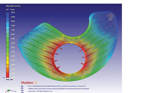
Mold filling simulation now provides a 3D-solver-based, scientific approach to determine the proper gating strategy and venting arrangement based on the predicted melt front. Simulation tools provide a series of features that enable mold designers to evaluate cold/hot runner scenarios with a
built-in template of gate/runner types. In facilitating such features, flow analysis predicts the required injection pressure and further estimates the required press size range.
Venting is always another major concern for mold builders. With the flow front analysis, air traps can be predicted and displayed in a 3D model. When air traps occur on a non-parting surface, they can be minimally improved by changing either the gate or the part thickness. When air traps occur on a parting surface, virtual vents can be set in the simulation tool to evaluate any improvement. 3D simulation tools using highly accurate theory will effectively avoid the risk of re-tooling and multiple tryouts.
The ability to evaluate different cooling arrangements can deliver more accurate cycle time estimation. Cycle time is always critical to OEMs and molders for meeting expected productivity levels. Without simulation, cycle time is estimated based on thickness distribution or past experience with similar part geometries. However, this estimation does not take into account cooling time for hot spots/undercuts or the potential cooling circuit efficiency.
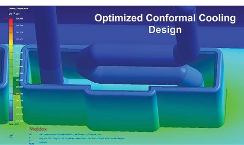
With modern 3D mold filling simulation software, it’s feasible to evaluate different cooling arrangements by comparing accurate cycle time based on the whole system, efficiency of each cooling loop, adequate cooling channel size and plastic frozen percentage.
An optimized cooling system will help to facilitate an improvement in mold temperature control, which helps to maintain a minimum cycle time. Cooling analysis also helps maintain part shrink and deflection, which can occur as a result of mold temperature differences between the core and cavity sides.
Mold design enhancements in relation to cooling will save customers significant time and effort down the road.
Integration with 3D CAD/CAM can boost efficiency. Many mold designers design molds only in their familiar CAD/CAM software and outsource the molding simulation, and this requires massive communication efforts. Today’s flow simulation tools can be accessed within mainstream 3D CAD/CAM software, and this helps any mold designer analyze his design efficiently in-house.
The integration of simulation with CAD/CAM streamlines the iterative mold design analysis process and shortens the development cycle significantly. Designers can easily compare cooling options for the hot area, including bubblers, baffles, higher-conductivity metal or even conformal cooling metal blocks manufactured by direct metal laser sintering (DMLS). Gate placement can be done in a few clicks to enable the designer to observe the flow pattern. Simulation software can provide a more precise mold-building cost/performance analysis for each of these options.
The simulation can facilitate proactive communication, which can assure a successful tool launch. Many common molding problems are caused by factors other than mold design, but mold builders historically have not gotten involved until the problems occur. Today’s successful mold builders are proactive. They get involved ahead of tooling kickoff and host review meetings with the part designers, molders and other suppliers as soon as simulation results are available. The 3D simulation tool can illustrate the potential problems and enables the team to address them before production with appropriate part or mold design changes.
Summary
A senior mold builder once told me, “Any mold design completed without using a mold filling tool cannot be called a good design.” I believe this holds true. Mold simulation tools can help mold builders better understand mold filling behavior and minimize lead times in the engineering process. Implementing simulation technology in-house can help mold builders remain competitive as well.
Related Content
What Is Scientific Maintenance? Part 1
Part one of this three-part series explains how to create a scientific maintenance plan based on a toolroom’s current data collection and usage.
Read MoreTolerancing in Mold Design, Part 2: Using GD&T to Address Conventional Tolerancing Issues
Mold designers can achieve a single interpretation of workpiece functionality when following the American Society of Mechanical Engineers Geometric Dimensioning and Tolerancing standard.
Read MoreThree Good Reasons to Switch from Three- to Five-Axis Machining in Moldmaking
Five-axis machining technology is a great tool in the moldmaker toolbox.
Read MoreMold Design Review: The Complete Checklist
Gerardo (Jerry) Miranda III, former global tooling manager for Oakley sunglasses, reshares his complete mold design checklist, an essential part of the product time and cost-to-market process.
Read MoreRead Next
How to Use Strategic Planning Tools, Data to Manage the Human Side of Business
Q&A with Marion Wells, MMT EAB member and founder of Human Asset Management.
Read MoreHow to Use Continuing Education to Remain Competitive in Moldmaking
Continued training helps moldmakers make tooling decisions and properly use the latest cutting tool to efficiently machine high-quality molds.
Read More
